Transmission line structure

a transmission line and transceiver technology, applied in printed circuits, waveguides, printed circuit details, etc., can solve the problems of common-mode noise generation, the need of conventional single-ended signal lines, etc., to reduce common-mode noise and capacitance, and low signal quality

Active Publication Date: 2015-12-31
CHUNG YUAN CHRISTIAN UNIVERSITY
View PDF0 Cites 1 Cited by
  • Summary
  • Abstract
  • Description
  • Claims
  • Application Information

AI Technical Summary

Benefits of technology

[0006]Because the conventional transmission line structure has a common problem of low signal quality due to large common-mode noise and high capacitance, it is a major object of the present invention to provide a transmission line structure to reduce common-mode noise and capacitance at the crossing area mainly by the ways of shrinking the line width and having the transmission lines on the upper layer close to each other and also shrinking the line width of the transmission line on the low layer.

Problems solved by technology

Meanwhile, with the industrial tendency toward high frequency and high speed, some communication related issues, such as electromagnetic interference (EMI), electromagnetic compatibility (EMC), signal integrity (SI), and power integrity (PI), become significant because of the increasing of transmission speed.
In detail, conventional single-ended signal lines cannot match the need of high frequency system to keep good signal integrity.
However, asymmetrical lines in the differential signal line pair will result in time difference of the received signals, which may cause the generation of common-mode noise.

Method used


Image

  • Transmission line structure
  • Transmission line structure
  • Transmission line structure

Examples


Embodiment Construction

[0035]There are various embodiments of the transmission line structure in accordance with the present invention, which are not repeated hereby. Only two preferred embodiments are mentioned in detail in the following paragraphs as an example. It should be understood by those skilled in the art that the preferred embodiments disclosed in the following paragraphs are merely an example instead of restricting the scope of the invention itself.

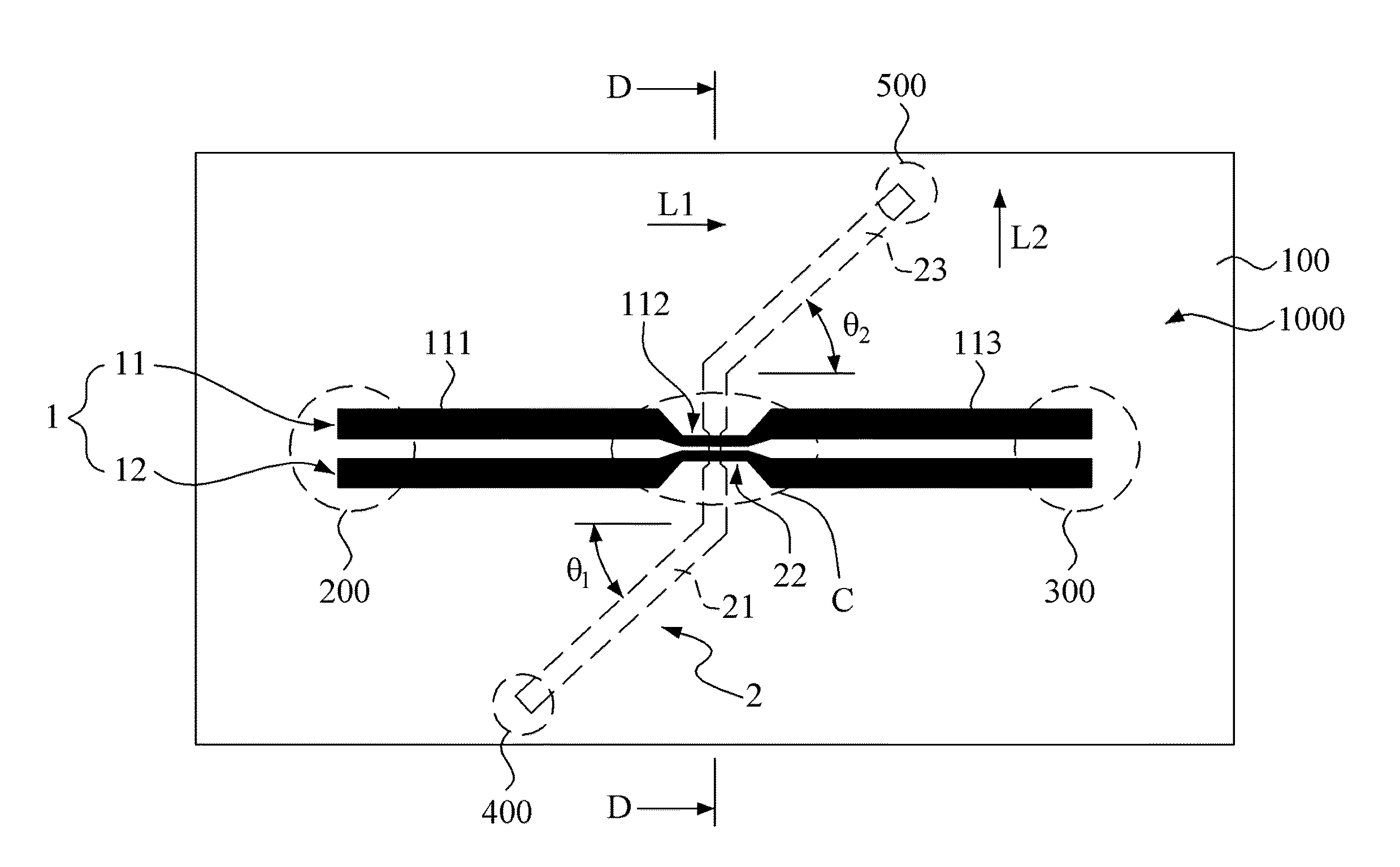
[0036]Please refer to FIGS. 3 to 4, wherein FIG. 3 is a schematic view showing a transmission line structure in accordance with a first embodiment of the present invention; FIG. 3A is a partially enlarged view of the transmission line structure of the crossing area C in FIG. 3 in accordance with the first embodiment of the present invention; and FIG. 4 is a cross-section view showing the transmission line structure taken along the line D-D′ in FIG. 3 in accordance with the first embodiment of the present invention.

[0037]As shown, a transmission line...


PUM


Abstract

A transmission line structure emplaces at a substrate which includes a first layout layer, a first dielectric layer, a second dielectric layer, a second dielectric layer, and a grounding layer includes a first transmission line pair and at least one second transmission line. The first transmission line pair is set on the first layout layer. The second transmission line is set on the second layout layer. A line of first transmission line pair and a line of the second transmission line cross each other and form a crossing area. A width of the line is narrow. A distance between the first transmission line pair and the second transmission line at the crossing area is less than a distance at an outstanding area.

Description

FIELD OF THE INVENTION[0001]The present invention relates to a transmission line structure, and more particularly, relates to a transmission line structure with lines close to each other at a crossing area.BACKGROUND OF THE INVENTION[0002]Attending with the developments of electronic technologies, more and more high frequency electronic products are available in the market, and digital signal transmission speed also becomes faster and faster. Meanwhile, with the industrial tendency toward high frequency and high speed, some communication related issues, such as electromagnetic interference (EMI), electromagnetic compatibility (EMC), signal integrity (SI), and power integrity (PI), become significant because of the increasing of transmission speed. Thus, signal quality and integrity has become a concern of circuit design.[0003]In detail, conventional single-ended signal lines cannot match the need of high frequency system to keep good signal integrity. Thus, most high frequency and h...

Claims


Application Information

Patent Timeline
Patent Type & Authority Applications(United States)
IPC IPC(8): H05K1/02H01P3/08
CPCH05K1/0228H01P3/08H05K1/0245H01P5/028H05K2201/09245H05K2201/09727H01P3/026H01P3/088
Inventor SHIUE, GUANG-HWA
Owner CHUNG YUAN CHRISTIAN UNIVERSITY
Why Eureka
Try Eureka