
Series-coupled fluidized bed reactor units including cyclonic plenum assemblies and related methods of hydrofluorination

a fluidized bed and reactor technology, applied in the field of series-coupled fluidized bed reactor units, can solve the problems of clogging the distributor's gas flow opening as an aggregate mass, affecting the cyclonic separation of hydrogen fluoride gas within the primary reaction chamber, and affecting the cyclonic separation

Active Publication Date: 2015-03-05
HONEYWELL INT INC
View PDF0 Cites 4 Cited by
  • Summary
  • Abstract
  • Description
  • Claims
  • Application Information

AI Technical Summary

Benefits of technology

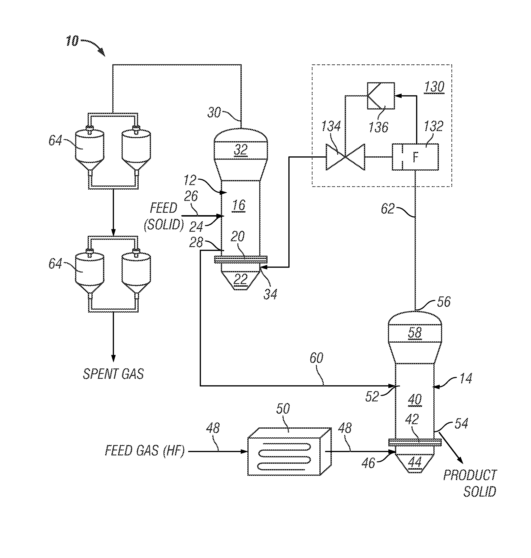
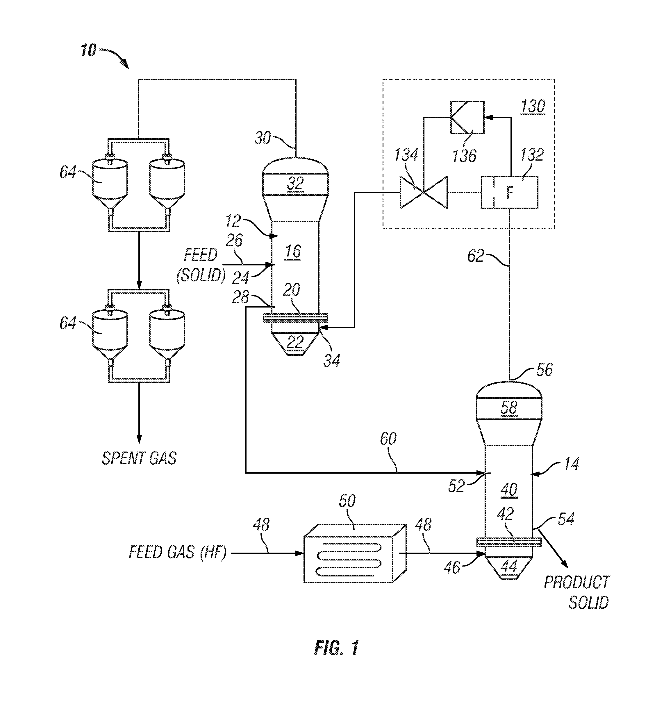
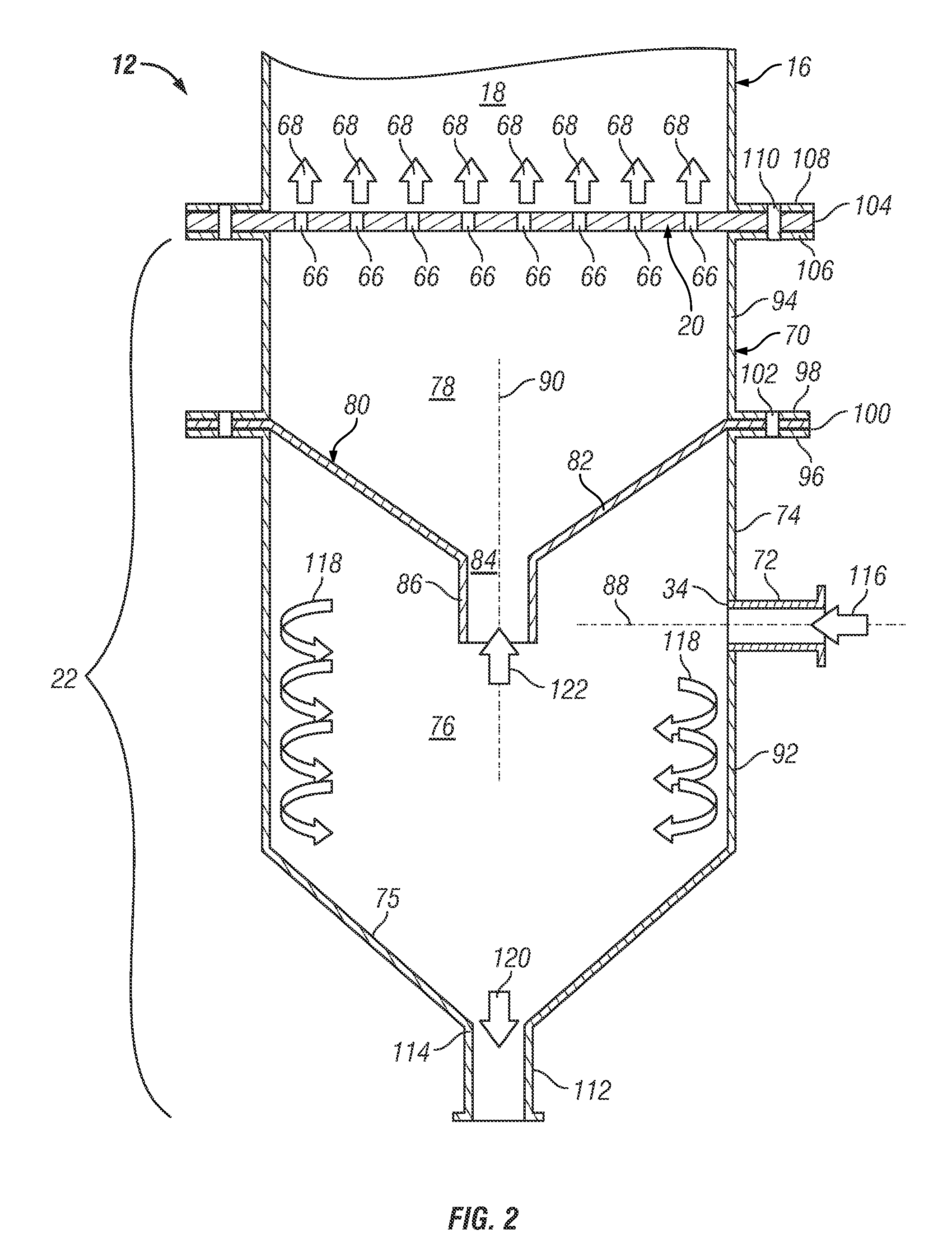
This patent describes a method of using two fluidized bed reactors in series. The first reactor has a gas distributor and a cyclonic plenum assembly with a gas / solids inlet pipe. This pipe induces a vortex flow, which helps separate solids from the partially-reacted gas before it enters the gas distributor. The second reactor has a partially-reacted gas outlet. The technical effect of this method is to improve the separation of gas and solids, leading to a higher quality product.

Problems solved by technology

The larger entrained particles, which may have diameters approaching those of the gas flow openings provided in the gas distributor, can potentially clog the distributor's gas flow openings as an aggregate mass.
Clogging of the distributor's gas flow openings not only impedes gas flow through the distributor, but also results in the maldistrubtion of hydrogen fluoride gas within the primary reaction chamber.
The maldistrubtion of HF gas reduces the overall efficacy of the hydrofluorination reaction and produces dead zones along the upper face of the gas distributor, which increase the likelihood of areas of extreme localized heating (commonly referred to as “hot spots”) developing within the reaction chamber.
Gas distributor clogging may ultimately necessitate shutdown of the hydrofluorination unit to allow cleaning of the gas distributor, which adds undesired expense and delay to the hydrofluorination process.
While one or more freestanding particulate filters may be disposed upstream of the primary hydrofluorinator to reduce the quantity of entrained solids reaching the gas distributor, such filters require routine maintenance to replace or clean of saturated filter elements and thus also necessitate periodic shutdown of the hydrofluorination unit.

Method used


Image

  • Series-coupled fluidized bed reactor units including cyclonic plenum assemblies and related methods of hydrofluorination
  • Series-coupled fluidized bed reactor units including cyclonic plenum assemblies and related methods of hydrofluorination
  • Series-coupled fluidized bed reactor units including cyclonic plenum assemblies and related methods of hydrofluorination

Examples


Embodiment Construction

[0012]The following Detailed Description is merely exemplary in nature and is not intended to limit the invention or the application and uses of the invention. Furthermore, there is no intention to be bound by any theory presented in the preceding Background or the following Detailed Description. As utilized herein, the term “pipe” encompasses all types of flow conduits, as well as assemblies of flow conduits joined in fluid communication.

[0013]Although described below in conjunction with a particular type of series-coupled fluidized bed reactor unit, namely, a multi-stage fluidized bed hydrofluorination reactor unit, embodiments of the reactor unit can assume any form wherein at least two reaction chambers are coupled in series, as considered with respect to the flow of a gaseous reactant; and wherein partially-reacted gas from a second reaction chamber, which is entrained with solid particulate matter, is directed into a gas distributor for injection into a first reaction chamber....


PUM

PropertyMeasurementUnit
outer diameteraaaaaaaaaa
flow rateaaaaaaaaaa
diametersaaaaaaaaaa

Abstract

Embodiments of a series-coupled fluidized bed reactor unit are provided. In one embodiment, the reactor unit includes primary and secondary reactors. The primary reactor includes a reaction vessel, a gas distributor fluidly coupled to the reaction vessel, and a cyclonic plenum assembly. The cyclonic plenum assembly includes a plenum assembly housing, which is fluidly coupled to the gas distributor and which has an annular sidewall; and a gas / solids inlet pipe, which fluidly couples a partially-reacted gas outlet of the secondary reactor to the plenum assembly housing. The gas / solids inlet pipe is tangentially positioned with respect to the annular sidewall of the plenum assembly housing to induce vortex flow within the plenum assembly housing of the partially-reacted gas received from the secondary fluidized bed reactor through the gas / solids inlet pipe to promote the cyclonic separation of entrained solids from the partially-reacted gas prior to entry into the gas distributor.

Description

TECHNICAL FIELD[0001]The present invention relates generally to fluidized bed processing and, more particularly, to embodiments of a series-coupled fluidized bed reactor unit including a cyclonic plenum assembly that minimizes clogging of the primary reactor's gas distributor, as well to hydrofluorination methods carried-out utilizing such a series-coupled fluidized bed reactor unit.BACKGROUND[0002]Fuel for nuclear power plants is produced by uranium enrichment processes requiring uranium hexafluoride (UF6) as a feed or input. UF6 is commonly produced by the fluorination of uranium tetrafluoride (UF4), which is, in turn, commonly produced utilizing a multi-stage hydrofluorination process. During a typical multi-stage hydrofluorination process, uranium dioxide (UO2) is introduced as a solid feed into a first fluidized bed hydrofluorination reactor (referred to herein as the “primary hydrofluorinator”) and contacted with partially-reacted hydrogen fluoride (HF) gas to produce partiall...

Claims


Application Information

Patent Timeline
Patent Type & Authority Applications(United States)
IPC IPC(8): B01J8/26C01G43/06
CPCC01G43/06B01J8/26B01J8/44C01G43/066B01J8/1818B01J8/28B01J8/0055B01J8/0085Y02E30/30
Inventor YANG, TERRISJOHNSON, ROBERTTUNG, HSUEH SUNG HARRY
Owner HONEYWELL INT INC
Learn More