Socket having overheating destructive limiting element
Active Publication Date: 2015-03-05
GREEN IDEA TECH INC
View PDF8 Cites 15 Cited by
Summary
Abstract
Description
Claims
Application Information
AI Technical Summary
This helps you quickly interpret patents by identifying the three key elements:
Problems solved by technology
Method used
Benefits of technology
Benefits of technology
The present invention provides a socket with an overheating destructive limiting element. The limiting element is an insulation material that prevents unintended contact with surrounding electronic elements after disconnecting power. The design simplifies the processing procedure and provides sufficient contact areas to mitigate temperature rise. The live wire terminals, live wire conductive plate, and neutral wire terminals are secure at a turn-on position to mitigate the rise in temperature when the current passes through. The live wire terminals and neutral wire terminals have fastening portions and positioning portions to ensure precise alignment with the live wire hole and neutral wire hole at the housing to effectively maintain a product yield rate. The live wire terminals and neutral wire terminals are "individually" in contact with their respective conductive plates, such that when one set of terminals disengages, the power-on state of other non-overheated terminals is maintained unaffected. The limiting element has a small volume, allowing individual power off of each socket unit without adding much volume.
Problems solved by technology
In the event of current overload, circuit overheating or an excessively high ambient temperature, the meltable metal is heated to cause a rise in the temperature and becomes molten and broken.
As a result, the two terminals intended to be disconnected may again erroneously come in contact to form close circuit.
If a part of the molten meltable metal remains stuck to the two terminals, the stuck molten meltable metal may also result in an erroneous contact between the two terminals to fail in a complete disconnection.
Further, the expelled molten meltable metal also has a chance of coming into contact with other surrounding electronic elements to cause a short circuit.
Therefore, such conventional solution is exposed to potential hazards and needs to be improved.
Thirdly, a conventional overload protector has a large volume.
Whether for storage, transportation or usage, such excessive volume inevitably causes complications and inconveniences.
Method used
Image
Click on the blue label to locate the original text in one second.
Reading with bidirectional positioning of images and text.
Examples
first embodiment
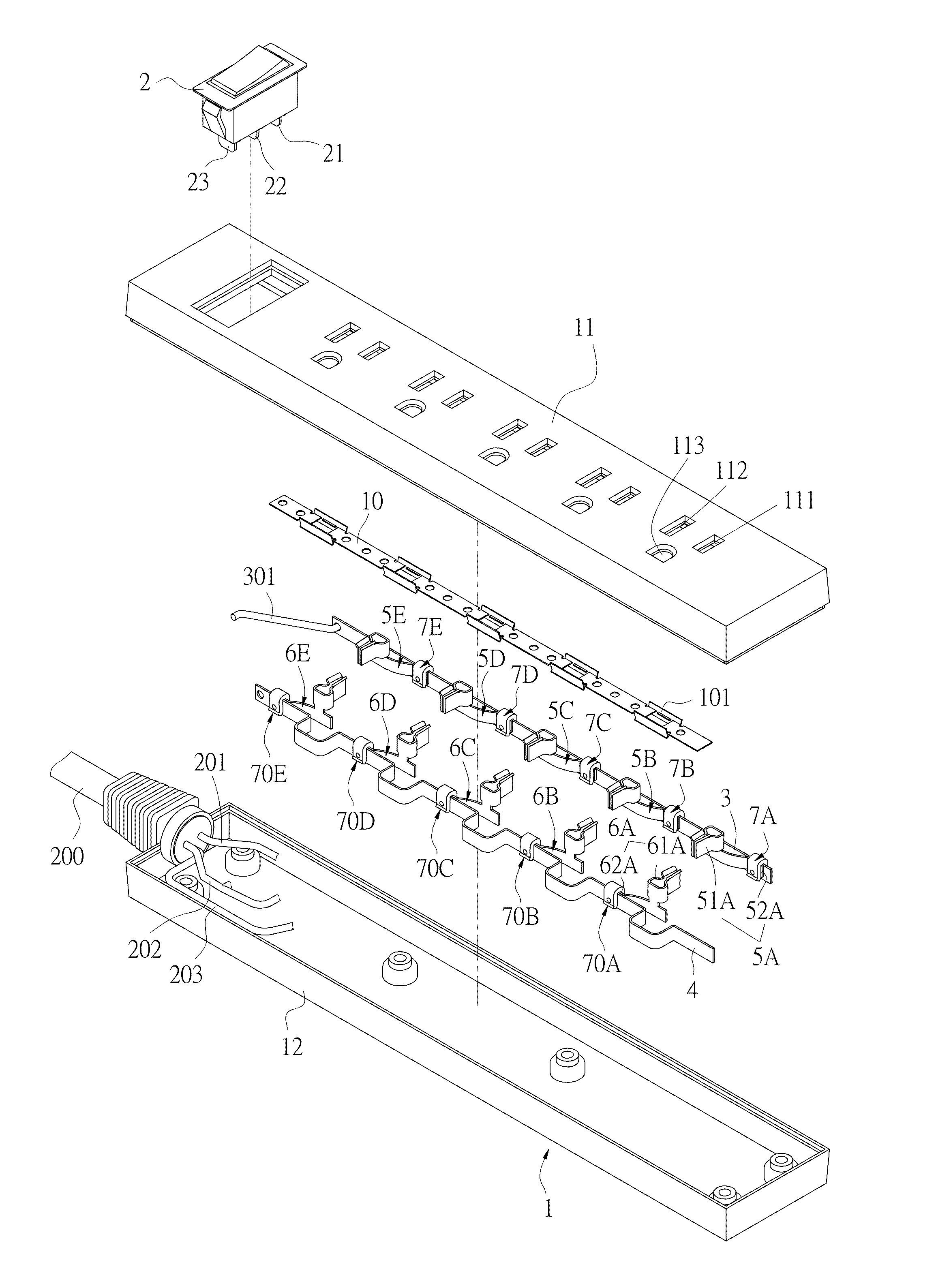
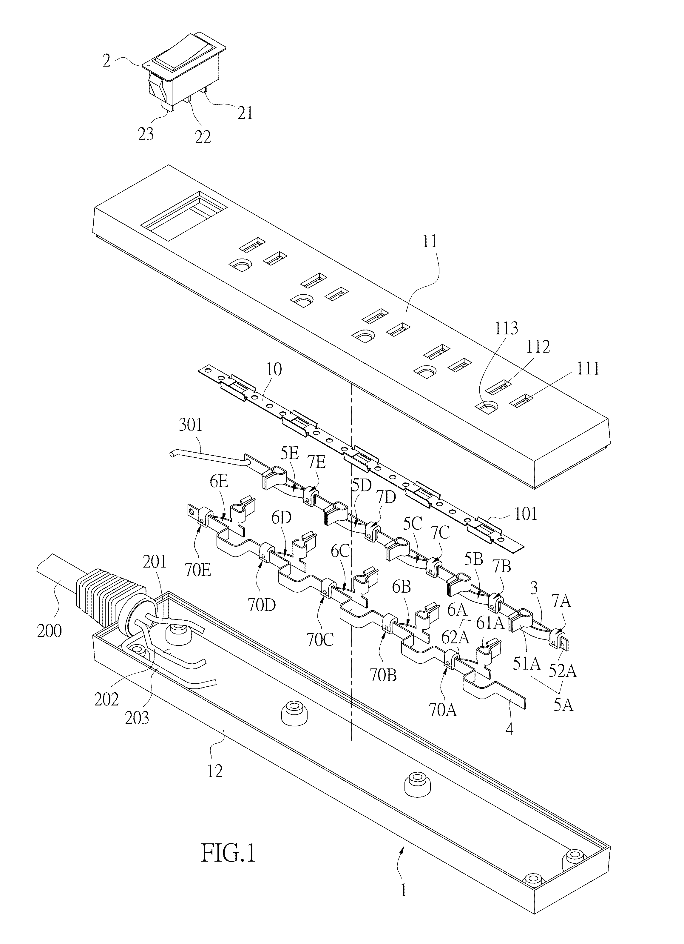
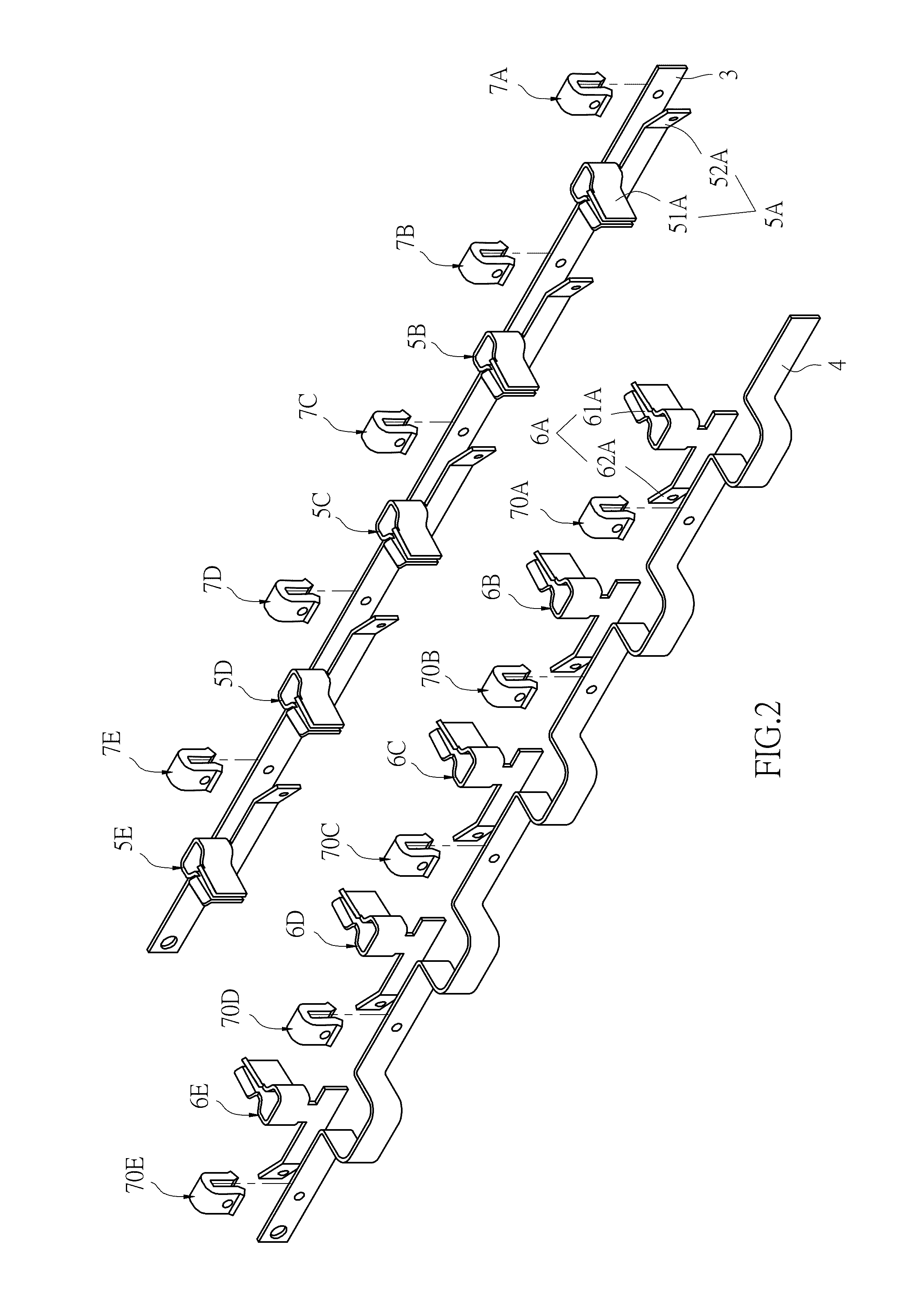
[0052]Referring to FIG. 1 and FIG. 2, a socket having an overheating destructive limiting element according to the present invention includes a housing 1, a switch 2, a live wire conductive plate 3, a neutral wire conductive plate 4, a plurality of live wire terminals 5A, 5B, 5C, 5D and 5E, a plurality of neutral wire terminals 6A, 6B, 6C, 6D and 6E, and a plurality of limiting elements 7A, 7B, 7C, 7D, 7E, 70A, 70B, 70C, 70D and 70E.
[0053]The housing 1 includes an upper casing 11 and a lower casing 12 that may be assembled to each other. The upper casing 11 includes a plurality of live wire holes 111 and a plurality of neutral wire holes 112.
[0054]The switch 2 includes a live wire input end 21, a live wire output end 22, and a neutral wire end 23. The live wire input end 21 is for connecting to a live wire conductive wire 201 of a power line 200. The neutral wire end 23 is for connecting to a neutral wire conductive wire 202 of the power line 200.
[0055]The live wire conductive plate...
sixth embodiment
[0074]FIG. 15A and FIG. 15B show the present invention. In the sixth embodiment, a limiting element 700D is formed by a pair of cover bodies 70 and 700 correspondingly combined to each other. For example, means for combining the cover bodies 70 and 700 may be ultrasonic welding, embedding or adhesion. The cover bodies 70 and 700 define chambers 701A and 701B, respectively, which are in communication with openings 702A and 702B of the chambers 701A and 702B, respectively. An inner side of the cover body 70 opposite the opening 702A is provided with a first insulation portion 71C, and an inner side of the other cover body 700 is correspondingly provided with the second insulation portion 72C, so as to clamp the live wire conductive plate 3A and the live wire contact portion 520A.
seventh embodiment
[0075]Referring to FIG. 16 also showing the present invention, the limiting element 700D is a ring body, and the first insulation portion 71D and the second insulation portion 72D of the limiting element 700D are both located at the inner side of the ring body. As such, the live wire conductive plate 3A and the live wire contact portion 520A are also similarly clamped to form the turn-on position.
PUM
Abstract
A socket having an overheating destructive limiting element includes a housing, a live wire conductive plate, a neutral wire conductive plate, at least one live wire terminal, at least one neutral wire terminal, and at least one limiting element. The live wire terminal includes a live wire contact portion in contact with the live wire conductive plate. The neutral wire terminal includes a neutral wire contact portion in contact with the neutral wire conductive plate. The limiting element is an insulating body, and is placed at contact parts of the live wire conductive plate and the live wire contact portion, and / or at contact parts of the neutral wire conductive plate and the neutral wire contact portion. When an operating temperature becomes excessively high, the limiting element becomes deformed and destructed to form a turn-off position.
Description
BACKGROUND OF THE INVENTION[0001]a) Field of the Invention[0002]The invention relates in general to a socket having an overheating destructive limiting element, and more particularly, to a socket having a limiting element made of an insulation material that positions a live wire terminal, a live wire conductive plate and / or a neutral wire terminal and a neutral conductive plate at a turn-on position. When an operating temperature gets too high, the limiting element becomes deformed and destructed to change the live wire terminal, the live wire conductive plate and / or the neutral wire terminal and the neutral conductive plate to a turn-off position.[0003]b) Description of the Prior Art[0004]To prevent a circuit from issues of current overload, short circuit and overheating, a fuse or an overload protector is usually provided at the circuit. When the temperature of the circuit gets too high or the current gets too large, the fuse affected by the high temperature becomes blown or a bi-...
Claims
Application Information
Patent Timeline
Application Date:The date an application was filed.
Publication Date:The date a patent or application was officially published.
First Publication Date:The earliest publication date of a patent with the same application number.
Issue Date:Publication date of the patent grant document.
PCT Entry Date:The Entry date of PCT National Phase.
Estimated Expiry Date:The statutory expiry date of a patent right according to the Patent Law, and it is the longest term of protection that the patent right can achieve without the termination of the patent right due to other reasons(Term extension factor has been taken into account ).
Invalid Date:Actual expiry date is based on effective date or publication date of legal transaction data of invalid patent.

