

Walking assistance moving vehicle
a technology for moving vehicles and assistance vehicles, applied in brake systems, process and machine control, instruments, etc., can solve the problems of inability to avoid obstacles, insufficient acceleration to stop devices before reaching obstacles, etc., and achieve the effect of avoiding obstacles
- Summary
- Abstract
- Description
- Claims
- Application Information
AI Technical Summary
Benefits of technology
Problems solved by technology
Method used
Image

Examples
first embodiment
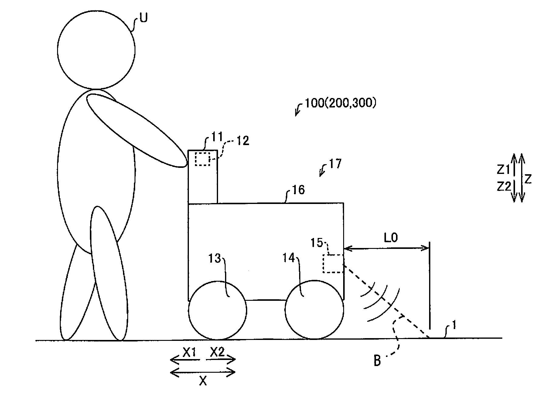
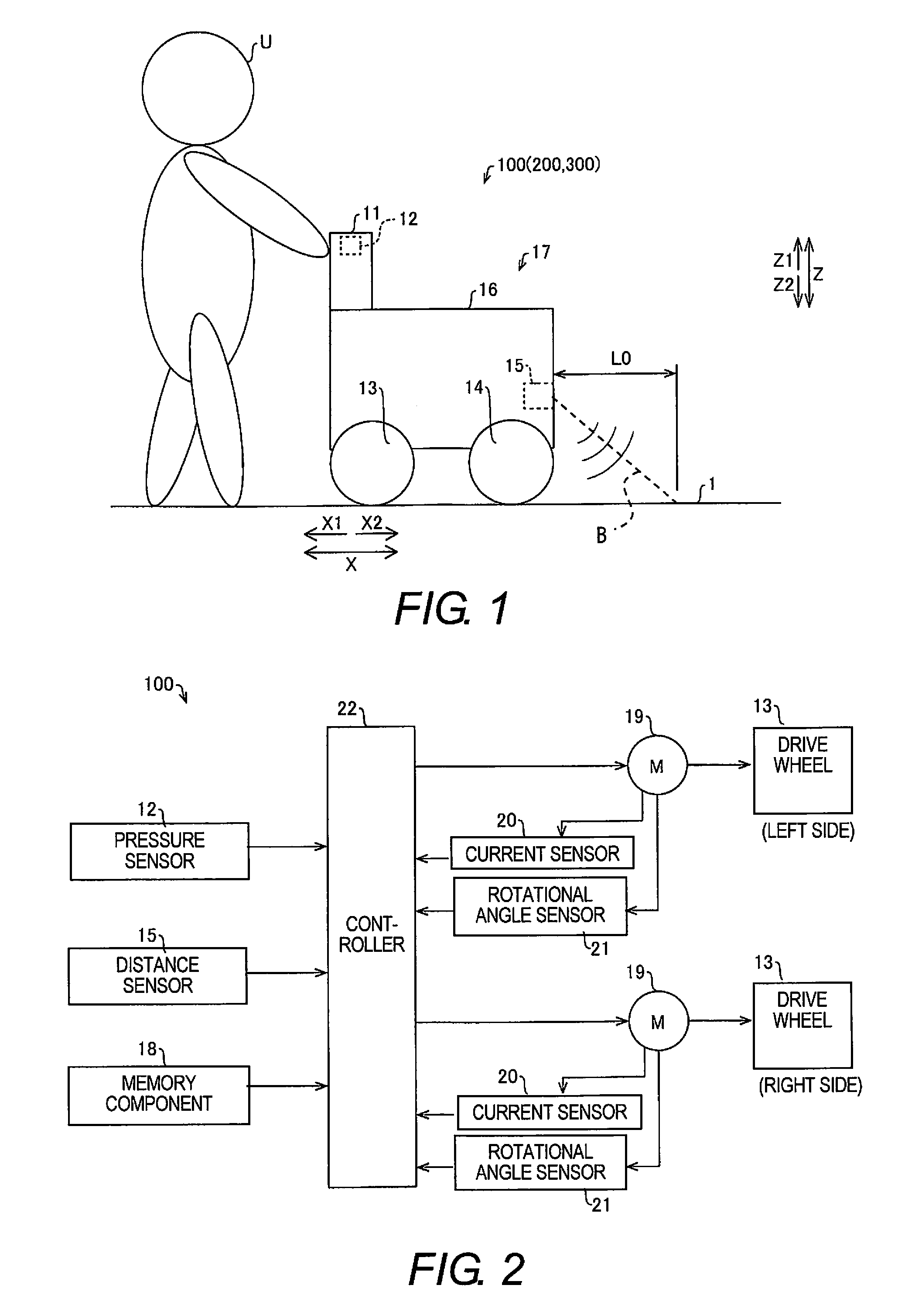
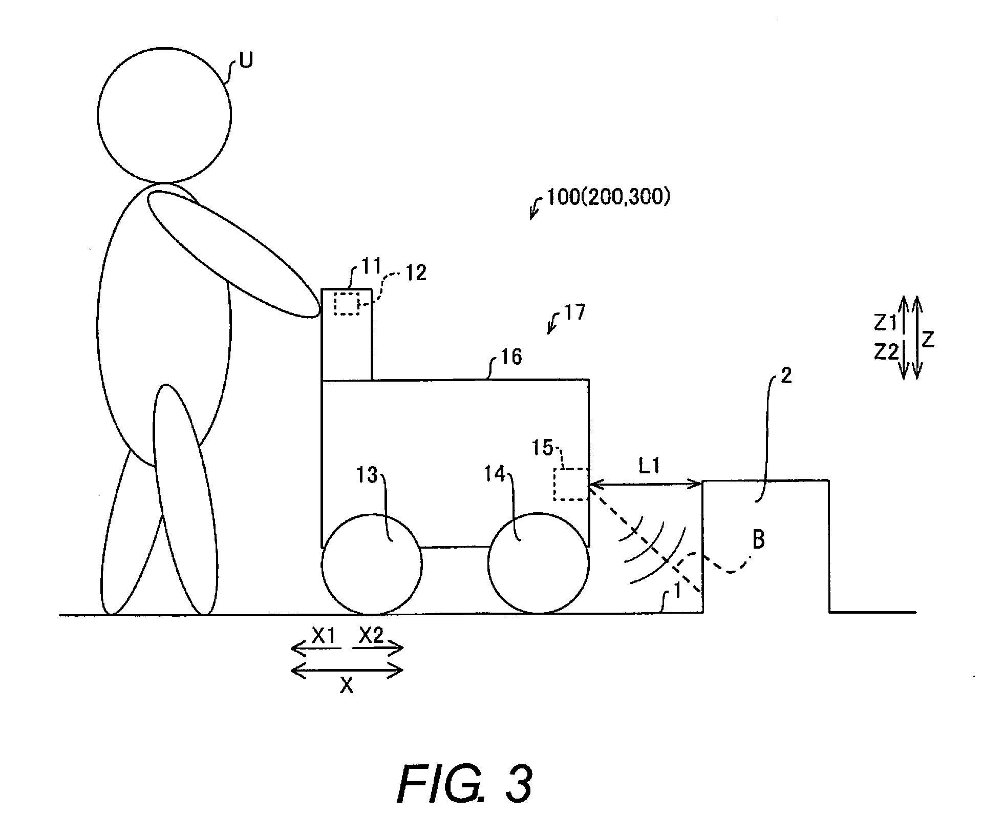
[0022]Referring to FIGS. 1 to 5, a walking assistance moving vehicle 100 is illustrated in accordance with a first embodiment.
[0023]As shown in FIG. 1, the walking assistance moving vehicle 100 in accordance with the first embodiment includes a grip component 11, a pressure sensor 12, a pair of left and right drive wheels 13, a pair of free wheels 14, a distance sensor 15, and a chassis 16. The grip component 11 is gripped by a user U. The pressure sensor 12 detects the input force imparted to the grip component 11. The left and right drive wheels 13 are driven by a pair of drive motors 19 (discussed below; see FIG. 2). The free wheels 14 rotate along with the movement of the drive wheels 13. In the illustrated embodiment, the walking assistance moving vehicle 100 has the pair of the free wheels 14. However, the number of the free wheels 14 can be different, such as one or more than three. The distance sensor 15 senses the distance ahead of the walking assistance moving vehicle 100 ...
second embodiment
[0047]Referring now to FIGS. 6 to 8, a walking assistance moving vehicle 200 in accordance with a second embodiment will now be explained. In view of the similarity between the first and second embodiments, the parts of the second embodiment that are identical to the parts of the first embodiment will be given the same reference numerals as the parts of the first embodiment. Moreover, the descriptions of the parts of the second embodiment that are identical to the parts of the first embodiment may be omitted for the sake of brevity. In this second embodiment, unlike in the first embodiment above, an example will be described of setting the threshold α according to the speed of the walking assistance moving vehicle 200.
[0048]As shown in FIG. 6, the walking assistance moving vehicle 200 in accordance with the second embodiment includes the pressure sensor 12, the distance sensor 15, a memory component 118, and an inclination sensor 123. The walking assistance moving vehicle 200 also i...
third embodiment
[0075]Referring now to FIG. 9, a walking assistance moving vehicle 300 in accordance with a third embodiment will now be explained. In view of the similarity between the first to third embodiments, the parts of the third embodiment that are identical to the parts of the first and second embodiments will be given the same reference numerals as the parts of the first and second embodiment. Moreover, the descriptions of the parts of the third embodiment that are identical to the parts of the first and second embodiments may be omitted for the sake of brevity. In this third embodiment, unlike in the second embodiment above, an example will be described in which no forward assist force is generated when a forward input force is detected in recovery processing from a stopped state.
[0076]The recovery processing from a stopped state of the walking assistance moving vehicle 300 in accordance with the third embodiment will be described through reference to FIG. 9. The parts of the processing ...
PUM
 Abstract
Description
Claims
Application Information