Jet mill combining high speed grinding apparatus and high speed griding apparatus with jet mill mounted thereon
- Summary
- Abstract
- Description
- Claims
- Application Information
AI Technical Summary
Benefits of technology
Problems solved by technology
Method used
Image

Examples
first embodiment
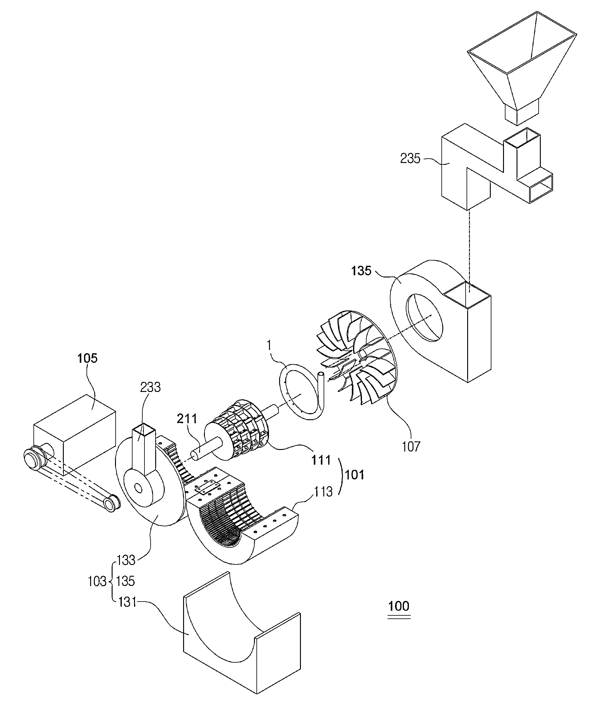
[0054]A jet mill 1 combining a high speed grinding apparatus as shown in FIG. 2 is combined with a high speed grinding apparatus according to the present invention as will be described in FIG. 5.
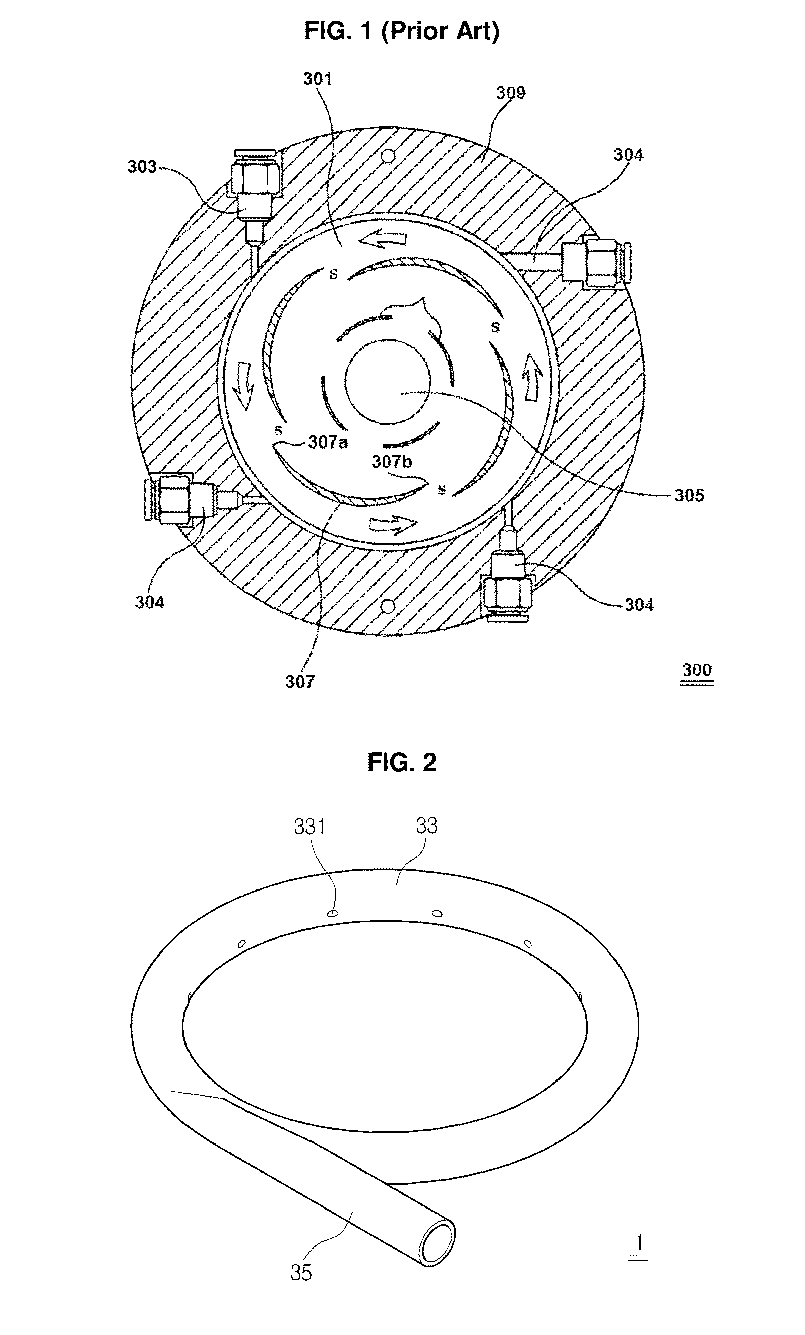
[0055]Further, the jet mill 1 combining a high speed grinding apparatus is a device that injects pressurizing air supplied from pressurizing air producing means (not shown) into grinded object introduced thereinto to generate swirling movements, thereby allowing the particles of the grinded object to collide against each other and making them become granules having fine sizes.
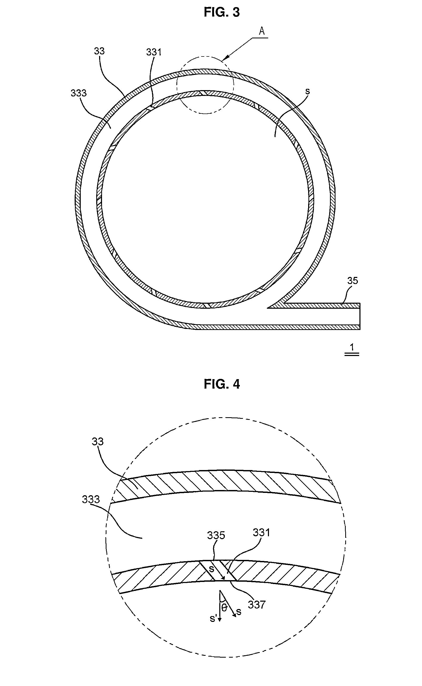
[0056]Furthermore, the jet mill 1 combining a high speed grinding apparatus is formed of a shape of a pipe having a moving passage 333 formed at the interior thereof, along which the pressurizing air moves, and includes a body 33 having end portions connected to each other like a shape of a ring and an inlet portion 35 coupled to one side of the body 33 to introduce the pressurizing air into the moving passage 333 forme...
second embodiment
[0194]FIG. 25 is an exploded perspective view showing a high speed grinding apparatus according to the present invention.
[0195]A high speed grinding apparatus 900 according to a second embodiment of the present invention has the same shape and structure as that of FIG. 5, while further including a first rotor 905 adapted to rotate a first rotary shaft 911 of a rotary blade part 910 and a second rotor 907 adapted to rotate a second rotary shaft 921 coupled to an impeller 107, wherein the rotary blade part 910 is coupled to the first rotary shaft 911 and rotated by the first rotor 905, and the impeller 107 is coupled to the second rotary shaft 921 and rotated by the second rotor 907.
[0196]That is, the first rotary shaft 911 is rotated by the first rotor 905 in such a manner as to be coupled rotatably to the side wall of the introduction part 133 on one end portion thereof, and the second rotary shaft 921 is rotated by the second rotor 907 in such a manner as to be coupled rotatably to...
PUM
 Abstract
Description
Claims
Application Information
 - Generate Ideas
- Intellectual Property
- Life Sciences
- Materials
- Tech Scout
- Unparalleled Data Quality
- Higher Quality Content
- 60% Fewer Hallucinations
Browse by: Latest US Patents, China's latest patents, Technical Efficacy Thesaurus, Application Domain, Technology Topic, Popular Technical Reports.
© 2025 PatSnap. All rights reserved.Legal|Privacy policy|Modern Slavery Act Transparency Statement|Sitemap|About US| Contact US: help@patsnap.com