LED light tube of module type

Inactive Publication Date: 2015-03-12
GEM WELTRONICS TWN CORP
View PDF13 Cites 3 Cited by
  • Summary
  • Abstract
  • Description
  • Claims
  • Application Information

AI Technical Summary

Benefits of technology

The present invention provides a modularized LED light tube with a narrow recess and a high-density arrangement of LED dies, which reduces production time and costs. The LED dies are coupled electrically via conductive elements and can be adjusted to achieve the densest arrangement. The LED light tubes of different lengths can be produced for different specifications, resulting in further cost reduction.

Problems solved by technology

The preceding several processes and assembly process and several structure of the LED units and the printed circuit plate are in fact not directly related to the LED light tube so that an overall manufacturing cost thereof cannot be reduced, thereby wasting a relatively large amount of materials.
The manufacturing cost is therefore high and consequently results in long manufacturing time.

Method used


Image

  • LED light tube of module type
  • LED light tube of module type
  • LED light tube of module type

Examples


Embodiment Construction

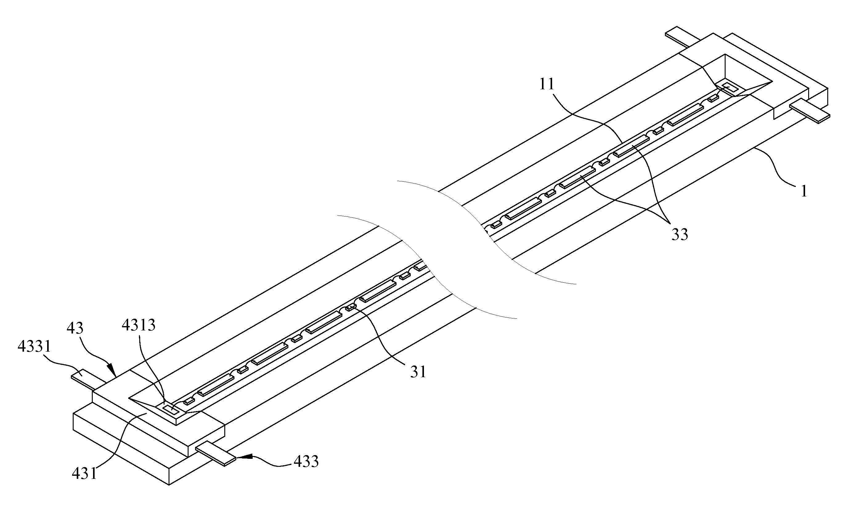
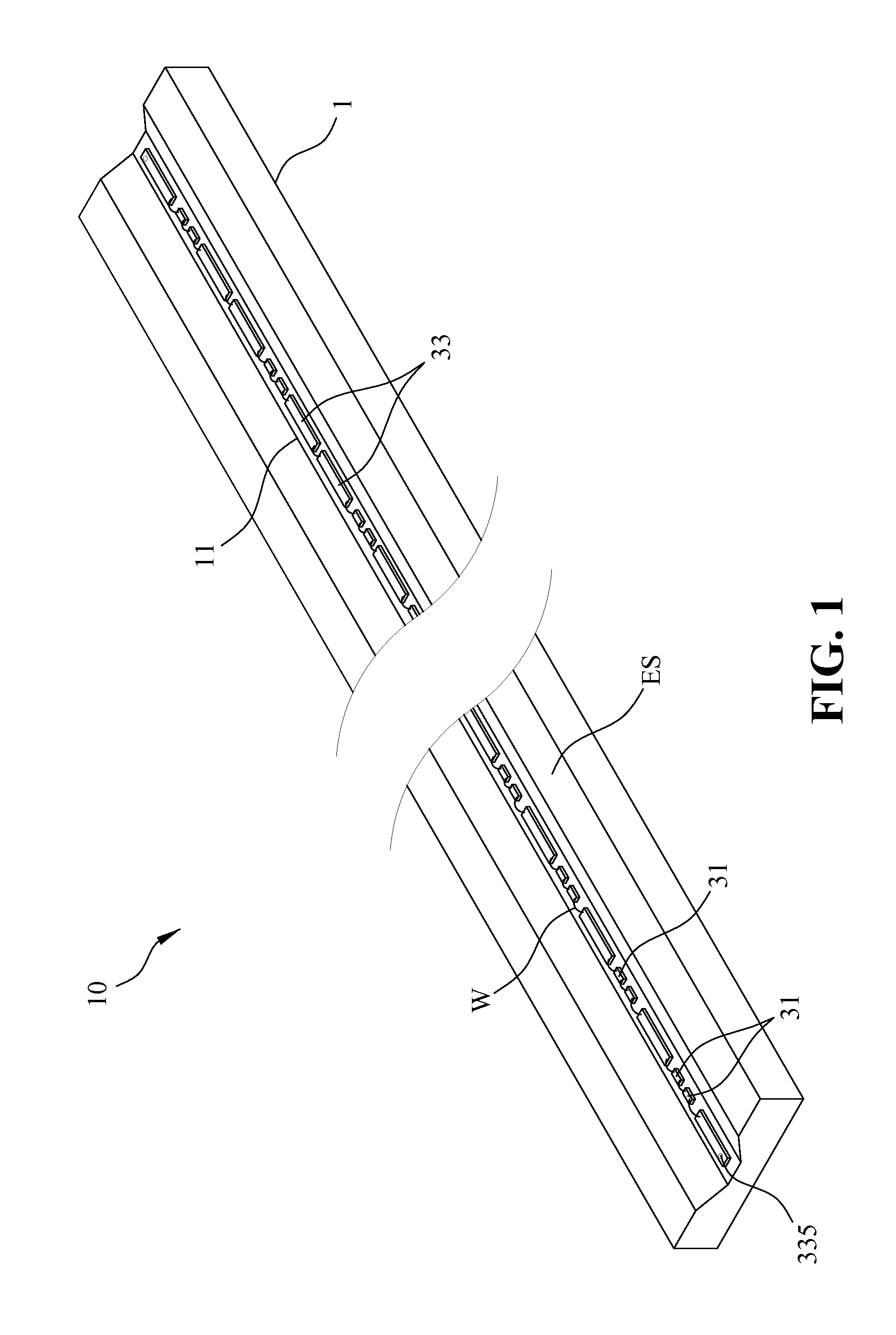
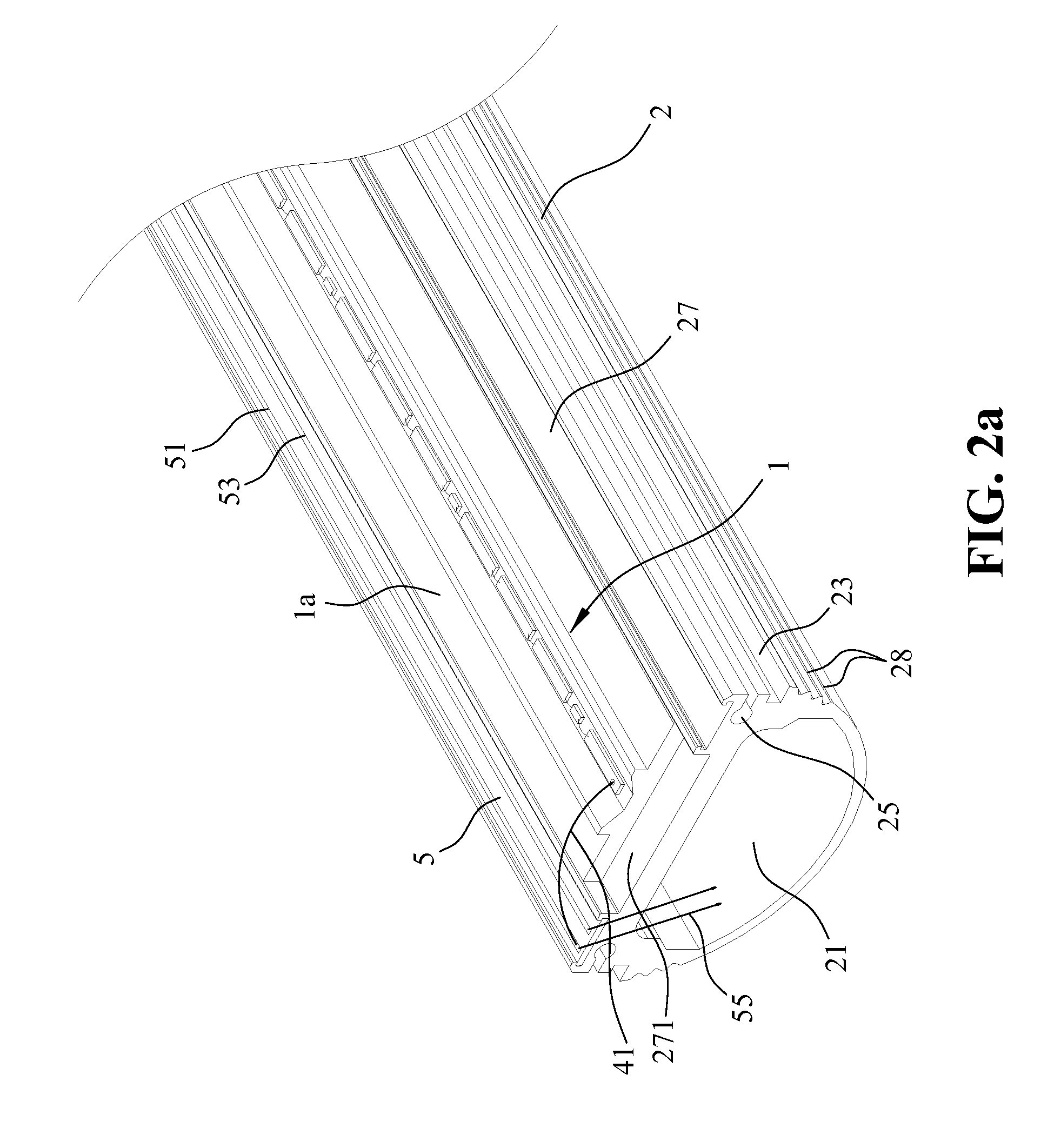
[0027]FIG. 1 shows a perspective view of a modularized LED base employed in an integrally formed light emitting diode (LED) light tube of the present invention. As shown in FIG. 1, the LED light tube 10 of module type according to the present invention includes a modularized LED base 1 having a light emitting side ES formed with a recess 11, at least one illumination unit and at least one bridging unit being fixed on a bottom surface of the recess 11. Preferably, the recess 11 has two lateral side walls extending inclinedly from two opposite sides of the bottom surface within a range of 40°˜65°.

[0028]In this embodiment, the illumination unit and the bridging unit are connected electrically via wire-bond technique, wherein the illumination unit is constituted by a plurality of LED dies 31 and the bridging unit is constituted by a plurality of conductive elements 33, one conductive element 33 is disposed between an adjacent pair of the LED dies 31 or one LED die 31 is disposed between...


PUM


Abstract

An LED light tube includes a modularized LED base having a recess, one illumination unit and one bridging unit being fixed in the recess, the illumination unit being constituted by LED dies and the bridging unit being constituted by conductive elements electrically connecting the LED dies; a heat dissipation base for receiving and supporting the modularized LED base thereon; a circuit unit disposed on the dissipation base to locate adjacent to one side of the recess; an optical layer covering the illumination unit and the bridging unit; a protection layer covering the optical layer; and a diffusion shield disposed above the dissipation base and having two peripheral sides formed with downwardly and inwardly bent projections slidably engaging two sliding grooves of the dissipation base, thereby enclosing the LED dies therein such that the diffusion shield is located above and transversely to a light emitting path of the LED dies.

Description

BACKGROUND OF THE INVENTION[0001]1. Field of the Invention[0002]The present invention relates to a light emitting diode (LED) light tube, more particularly to a module type integrally formed LED light tube including a modularized LED base and a modularized wire-holding frame unit.[0003]2. The Prior Arts[0004]Owing to high efficiency, long lasting, small size, low energy consuming, swift in response, and mature advance in the modern electronics lately, a majority of traditional light bulbs or light tubes are gradually replaced with LED light tubes. It is in the trend of research how to apply the LEDs in the mostly and highly used fluorescent lamps.[0005]A prior art LED light tube generally includes a light tube, a heat dissipation plate, a printed circuit board, a plurality of LED units and two conductive caps. The heat dissipation plate is mounted within the light tube while the printed circuit board is mounted on the heat dissipation plate. The LED units are connected electrically ...

Claims


Application Information

Patent Timeline
IPC IPC(8): F21V29/00F21K99/00
CPCF21V29/22F21V29/2206F21K9/50F21K9/30F21K9/20F21K9/27F21K9/90F21V29/76
Inventor HWU, JON-FWUWU, YUNG-FULIU, KUI-CHIANG
Owner GEM WELTRONICS TWN CORP
Why Eureka
Try Eureka