Multi-phase transformer type dc-dc converter

Inactive Publication Date: 2015-03-12
RENESAS ELECTRONICS AMERICA
View PDF11 Cites 16 Cited by
  • Summary
  • Abstract
  • Description
  • Claims
  • Application Information

AI Technical Summary

Benefits of technology

The patent describes a multi-phase transformer type DC-DC converter that has multiple DC-DC converters with transformers connected in parallel between an input and output. A circuit generates multiple clock signals that are phase-shifted with each other for use by the multiple converters. The technical effect is a more efficient and reliable DC-DC conversion process with improved stability and control over voltage and current.

Problems solved by technology

Large data centers contain rows and rows of server racks, which consume substantial amounts of power at a high cost.
Some data centers consume power more than 100 times that of a typical office building.
For large power consuming data centers, electricity costs are a dominant operating expense and can account for over 10% of the total cost of ownership.

Method used


Image

  • Multi-phase transformer type dc-dc converter
  • Multi-phase transformer type dc-dc converter
  • Multi-phase transformer type dc-dc converter

Examples


Embodiment Construction

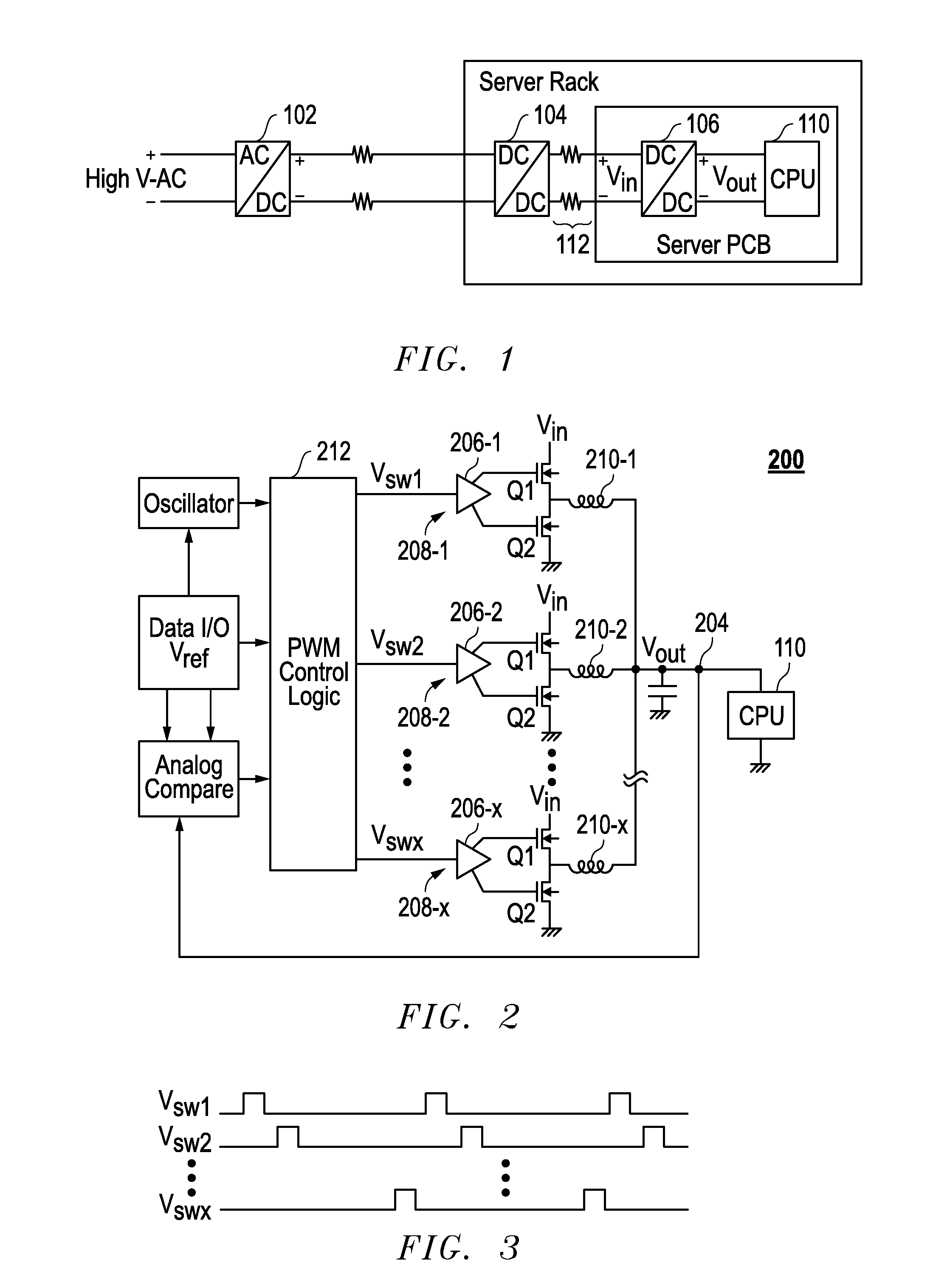
[0019]FIG. 1 illustrates a portion of an example system for distributing power to integrated circuits (e.g., CPUs) in server racks in a data center. For purposes of explanation only, the present invention will be described with reference to distribution of power to CPUs mounted on server printed circuit boards (PCBs) within server racks of a data center, it being understood the present invention should not be limited thereto.

[0020]With continuing reference to FIG. 1, AC-DC converter 102 is configured to convert high voltage, low current AC power into high voltage, low current DC power. An intermediate power transmission line transmits the high voltage, low current DC power from converter 102 to at least one rack of servers. The intermediate power transmission line contains resistive elements. Because power is transmitted at low current, these resistive elements consume relatively small amounts of power.

[0021]Server racks typically contain DC-DC converters, such as DC-DC converter 10...


PUM


Abstract

A multi-phase transformer type DC-DC converter. In one embodiment, the multi-phase transformer type DC-DC converter includes a plurality of DC-DC converters comprising a plurality of transformers, respectively, wherein the plurality of DC-DC converters are coupled in parallel between an input and an output. A circuit is coupled to the plurality of DC-DC converters and configured to generate a plurality of clock signals for use by the plurality of DC-DC converters, respectively, wherein the plurality of clock signals are phase shifted with respect to each other.

Description

RELATED APPLICATIONS[0001]This application claims the domestic benefit under Title 35 of the United States Code §119(e) of U.S. Provisional Patent Application Ser. No. 61 / 875,143, filed on Sep. 9, 2013, entitled “Multi-Phase Transformer Type DC-DC Converter,” which is hereby incorporated by reference in its entirety and for all purposes as if completely and fully set forth herein.BACKGROUND OF THE INVENTION[0002]Large data centers contain rows and rows of server racks, which consume substantial amounts of power at a high cost. Some data centers consume power more than 100 times that of a typical office building. For large power consuming data centers, electricity costs are a dominant operating expense and can account for over 10% of the total cost of ownership.[0003]Local utilities provide power to data centers via power lines that have resistive elements R, which consume power P as a function current I (i.e., P=I2R). Utilities prefer to transmit power at high voltage and low curren...

Claims


Application Information

Patent Timeline
IPC IPC(8): H02M3/335
CPCH02M3/33507H02M3/1584H02M3/1586
Inventor SATO, TETSUOAYUKAWA, KAZUHITOMURAKAMI, HIROSHI
Owner RENESAS ELECTRONICS AMERICA
Why Eureka
Try Eureka