Patent latency monitoring in software-defined networks

US20150071108A1Active Publication Date: 2015-03-12NEC CORP

Image

  • Patent latency monitoring in software-defined networks
  • Patent latency monitoring in software-defined networks
  • Patent latency monitoring in software-defined networks

Examples


Embodiment Construction

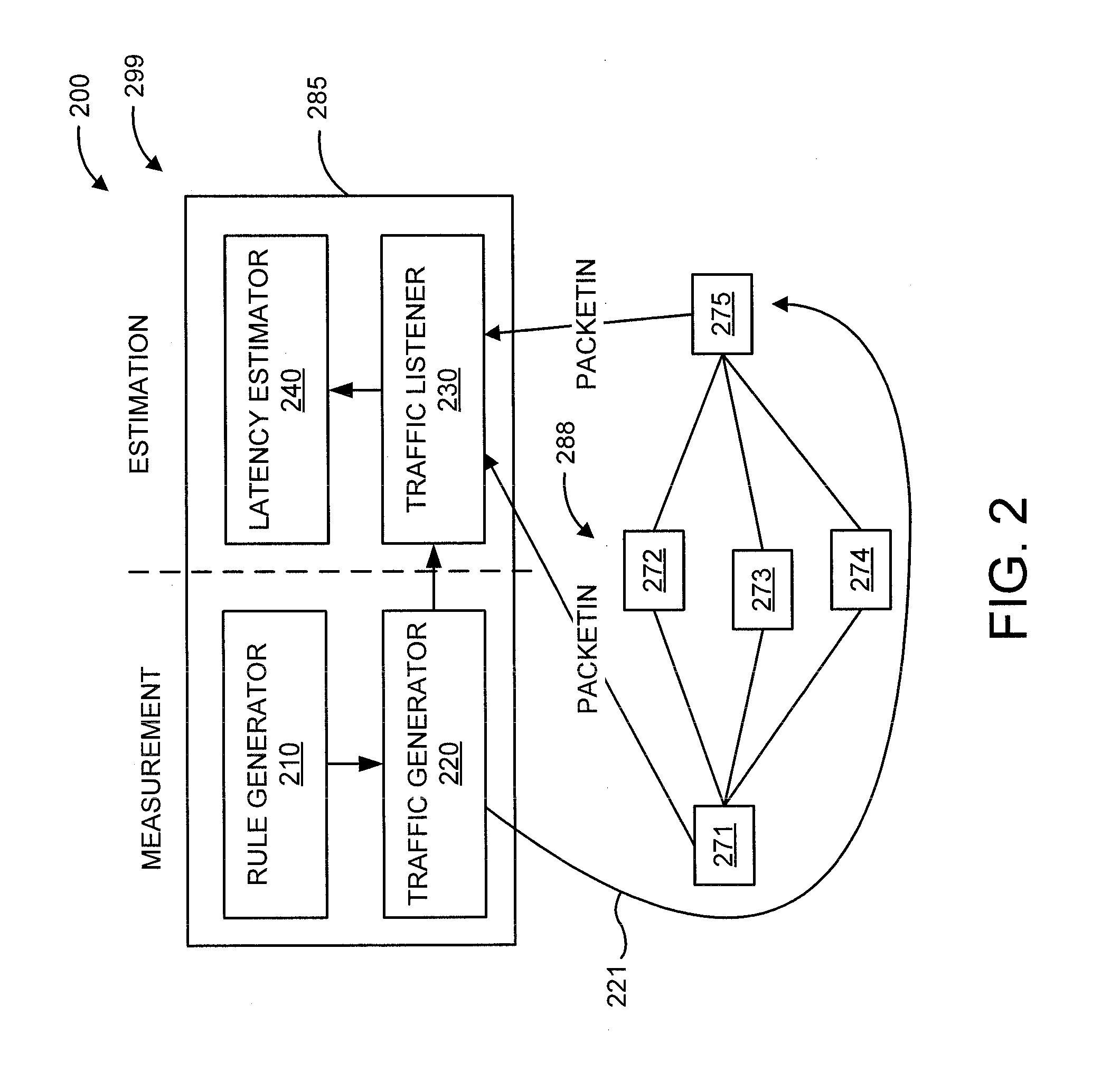
[0016]In various embodiments of the present principles, the present principles use software-defined networking (SDN) to estimate the latency of a network path. SDN separates the control and data planes of a network and provides an open communication interface between them. Most of the network control functionality is outsourced from switches and delegated to a centralized server (the controller), whereas switches focus only on forwarding packets. The controller and switches communicate with each other using a specialized protocol such as, for example, OpenFlow. With OpenFlow, switches have the ability to asynchronously notify the controller of network events (e.g., when a new flow arrives and there are no matching entries for it in the flow table or when the match action indicates it specifically).

[0017]We estimate the latency of a network path by comparing the timestamps of PacketIn messages sent by switches at the ends of the path and associated with each packet. A switch sends Pa...


PUM


Abstract

In a software defined network having switches including first and last switches and intermediate switches, wherein a default routing path exists between the first and last switches, a system and method are provided for computing path latency. The method includes inserting a respective monitoring rule(s) in each switch, mandating for each switch, forwarding a received rule matching packet to a next switch, and further mandating for the first switch and the last switch, sending a PacketIn message to a controller. The method includes inserting, in each switch, a respective monitoring probe(s) matching the respective monitoring rule(s) in a same switch to initiate mandates specified by the respective monitoring rule(s) in the same switch responsive to an arrival of the packet thereat. The method includes time-stamping the PacketIn messages to generate PacketIn timestamps, aggregating the PacketIn timestamps, and estimating the path latency from an aggregation of PacketIn timestamps.

Description

RELATED APPLICATION INFORMATION[0001]This application claims priority to provisional application Ser. No. 61 / 874,424 filed on Sep. 6, 2013, incorporated herein by reference.BACKGROUND[0002]1. Technical Field[0003]The present invention relates to networks, and more particularly to path latency monitoring in software-defined networks.[0004]2. Description of the Related Art[0005]Network latency contributes to the performance of many data center applications such as search, e-commerce, and banking Such applications often have several distributed components that need to communicate across low-latency network paths to reduce user response time and maximize provider revenue. To effectively manage the data center network and provide low-latency paths to applications, operators must continually monitor the latency on all paths and quickly route the traffic away from paths with high delay.[0006]To monitor the network paths latency, data center operators have two perspectives: from the applica...

Claims


Application Information

Patent Timeline
12 Mar 2015
Publication
US20150071108A1
IPC
H04L12/26; H04L45/42
CPC
H04L43/062; H04L43/0852; H04L43/106; H04L43/20
Inventors
LUMEZANU, CRISTIAN; YU, CURTIS