Remotely Installed Fuel Transfer Tube Closure System

a technology of fuel transfer tube and closure cover, which is applied in the direction of machines/engines, greenhouse gas reduction, nuclear elements, etc., can solve the problems of high cost of refueling nuclear power plants, increased radiation dose for workers, and high cost of reinstallation

Active Publication Date: 2015-03-12
PREFERRED UTILITIES MFG
View PDF3 Cites 5 Cited by
  • Summary
  • Abstract
  • Description
  • Claims
  • Application Information

AI Technical Summary

Problems solved by technology

The time it takes to refuel a nuclear power plant is very costly because of the replacement power which has to be purchased during such time.
The reinstallation is particularly time consuming and exposes workers to additional radiation dose because the bolts must be tightened to a prescribed torque in several passes in a specified sequence to achieve a full compression on the O-rings seals to assure a leak proof seal.
The containment area is hot and contains sufficient radiologic contamination to expose the operators to significant radiation.
So called quick release hatches or covers generally have complex latching mechanisms including a plurality of radially outwardly and inwardly slidable locking bolts that must align with and slide into latch receiving openings on a locking ring that is added to the flange weldment on the fuel transfer tube, and therefore are not suitable for use on existing fuel transfer tube flange weldments.

Method used


Image

  • Remotely Installed Fuel Transfer Tube Closure System
  • Remotely Installed Fuel Transfer Tube Closure System
  • Remotely Installed Fuel Transfer Tube Closure System

Examples


Embodiment Construction

OF THE INVENTION

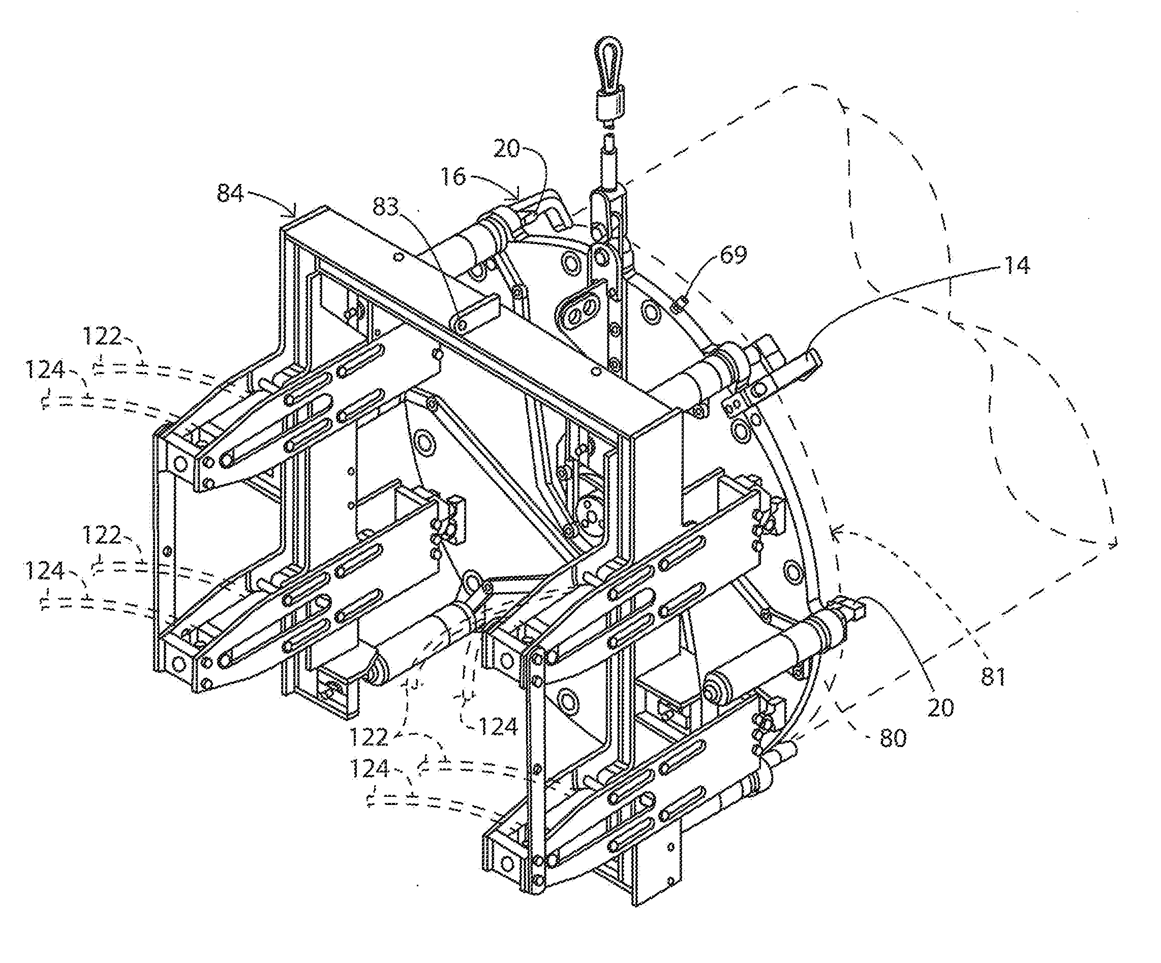
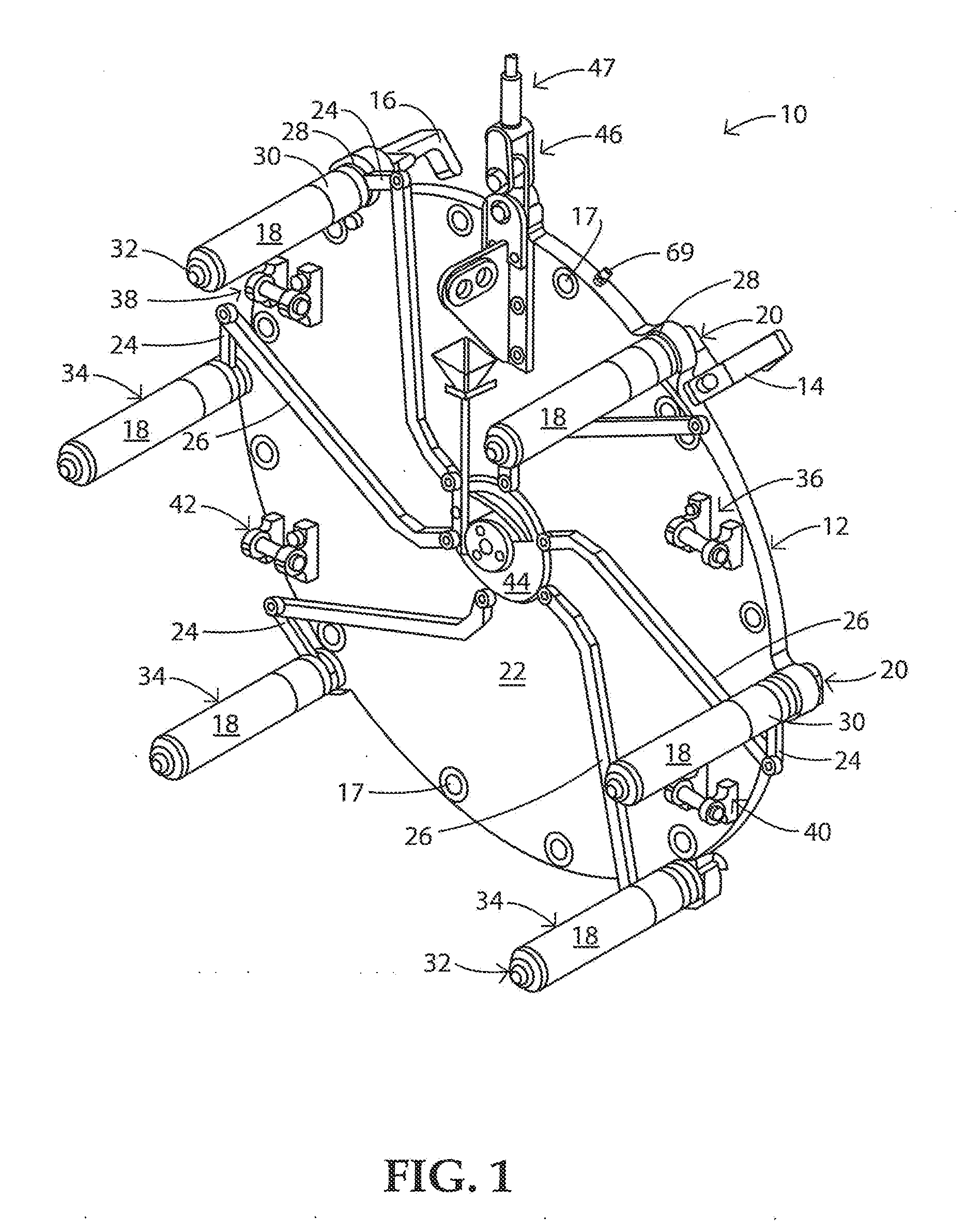
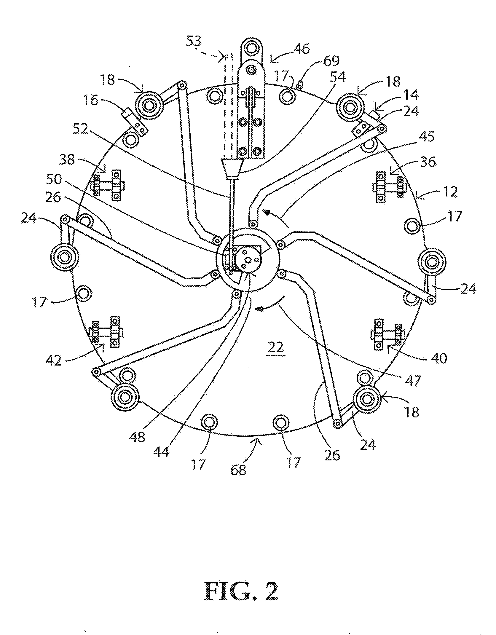
[0031]Turning now to the drawings an example of a remotely installed fuel closure system embodying the present invention is illustrated therein and in particular to FIGS. 1-4, a flange cover assembly generally designated 10 is a remotely installed flange and clamping mechanism. The flange cover assembly 10 can be installed from the refuel floor level approximately 33 feet above the fuel transfer tube fixed flange. The flange cover assembly 10 includes the same size and type of O-rings as used on known flange covers in the prior art to sealingly cover the opening of the fuel transfer tube. The flange cover assembly 10 also includes an arrangement for testing leakage in the space between the O-rings which is known as a local leak rate test of “LLRT” for short. Two centering guide hooks 14, 16 are bolted or otherwise suitably attached to the upper edges of the flange cover 12. The centering guides 14, 16 are sized to allow the flange cover assembly 10 to be supported ve...


PUM


Abstract

A system, method and apparatus for remotely installing a flange cover assembly on a fuel transfer tube fixed flange in a containment pit in a nuclear power plant is presented. In one example, the flange cover assembly includes J-bolt spring assemblies in which the feet of the J-bolt are rotated between a clamping and non-clamping orientation to engage with the rear face of the fixed flange. A tool frame is lowered into the containment pit to engage with the flange cover assembly to compress the J-bolt springs and extend the J-bolt foot toward and away from the flange cover. Dual acting cylinders move a spring compression frame on the frame tool to compress and relax the J-bolt spring assemblies.

Description

CROSS-REFERENCE TO RELATED APPLICATION[0001]The present application claims priority to provisional application Ser. No. 61 / 835,990, filed Jun. 17, 2014, which is incorporated herein in full by reference.FIELD OF THE INVENTION[0002]The present invention relates generally to flange closure systems for fuel transfer tubes in nuclear power plants and deals more particularly with a remotely installed fuel transfer tube system flange closure cover and a tool for installing and uninstalling a flange cover to a fuel transfer tube fixed flange.[0003]The present invention also relates to a method for remotely installing and uninstalling a flange cover on a fuel transfer tube fixed flange.BACKGROUND OF THE INVENTION[0004]The time it takes to refuel a nuclear power plant is very costly because of the replacement power which has to be purchased during such time. It is common in the operation of nuclear reactors to provide a flange cover to create a full and complete seal between the nuclear powe...

Claims


Application Information

Patent Timeline
Patent Type & Authority Applications(United States)
IPC IPC(8): G21C19/02
CPCG21C19/02F16J13/06F01D25/243G21C13/06Y02E30/30
Inventor DEFAZIO, JR., BERNARD
Owner PREFERRED UTILITIES MFG
Why Eureka
Try Eureka