Automated Stabilizing Apparatus

a stabilizing apparatus and automatic technology, applied in the direction of instruments, stands/trestles, camera body details, etc., can solve the problems of low torque, bulky devices and general difficulty in operation, and shaky videos, and achieve the effects of low manufacturing cost, simple use, and versatile adaptability

Inactive Publication Date: 2015-03-12
HOANG CHI KHAI
View PDF2 Cites 76 Cited by
  • Summary
  • Abstract
  • Description
  • Claims
  • Application Information

AI Technical Summary

Benefits of technology

[0006]It is the object of the present invention to provide an automatic stabilizer apparatus using a differential gear configuration that is compact, lightweight, attractive, simple to use, inexpensive to manufacture, and versatile in adapting to multiple types of imaging devices.

Problems solved by technology

When shooting videos using an imaging device such as a camera phone or a light camcorder, hand and body movements tend to transmit to the camera thus producing shaky videos.
In general, these techniques work well for small vibrations measured within a few degrees of movement, however, larger rotating movements of the camera associated with walking or running requires other external devices to stabilize the camera.
There are a few disadvantages to this design.
The device is bulky and general difficult to operate due to the inherent lack of controls in pitching or panning motion.
While brushless gimbals are relatively easy to use when paired with a predefined camera, however the low torque, brushless motors require calibration when used with cameras of slightly difference in weight.
Also, a unique mounting bracket is needed for cameras of different geometries such that the center of gravity of the camera has to be in line with the center axis of motor rotation at all times. This makes the brushless gimbal not conveniently adaptable to different camera types, and therefore most manufacturers simply make a unique brushless gimbal for one or two of the most popular camera models.
Lastly, the configuration of the brushless motors relative to the camera prevents the operator to view the camera screen during operation.

Method used


Image

  • Automated Stabilizing Apparatus
  • Automated Stabilizing Apparatus
  • Automated Stabilizing Apparatus

Examples


Embodiment Construction

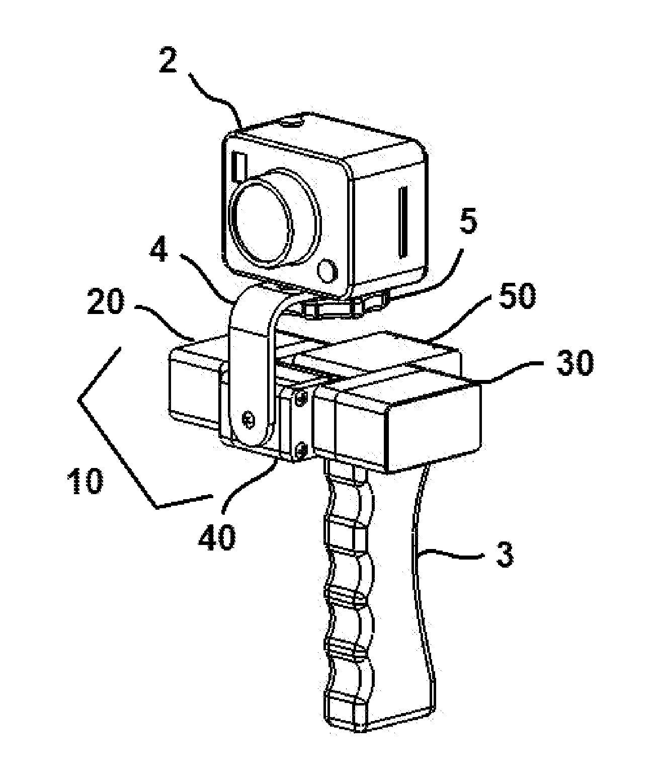
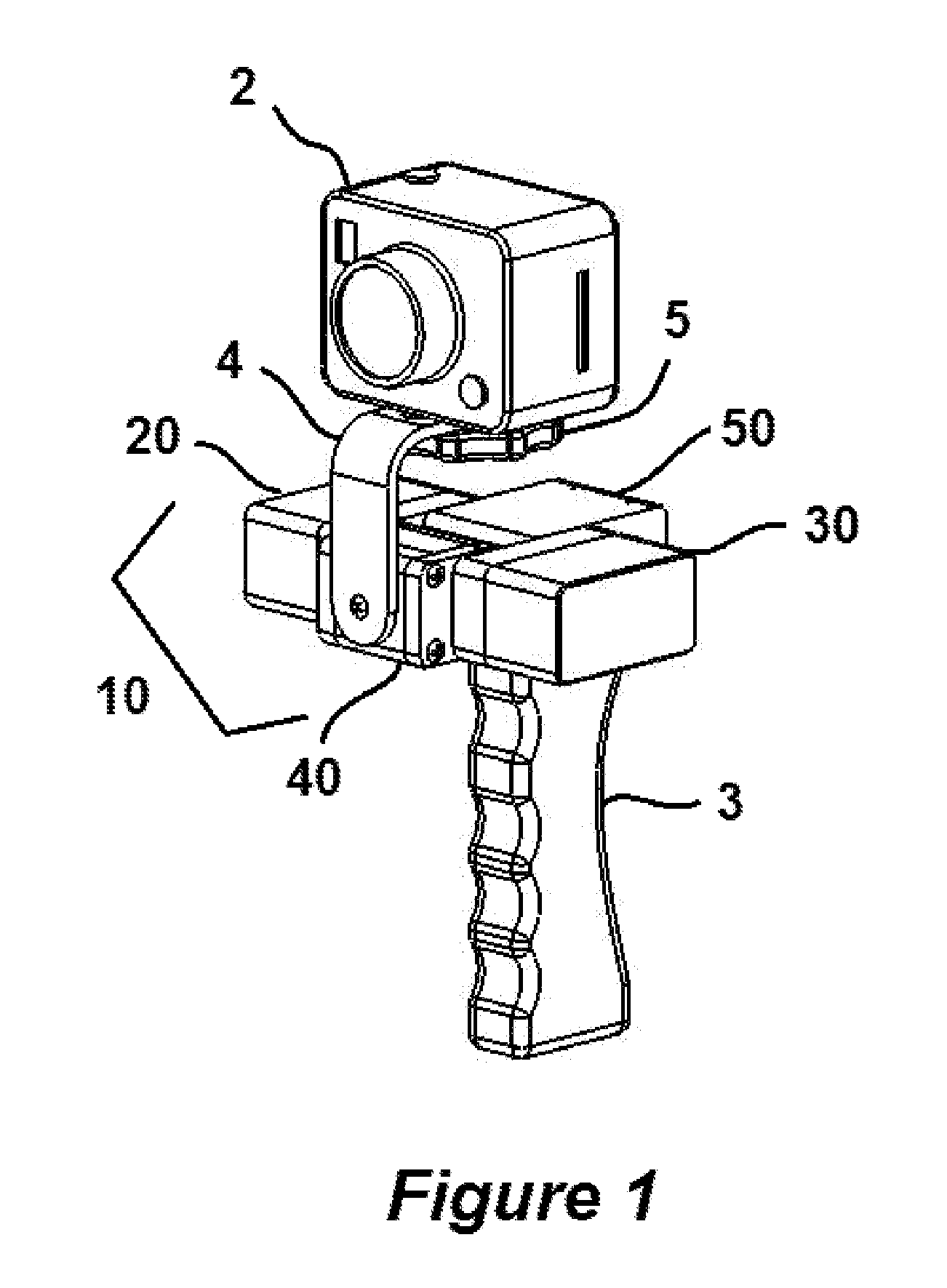
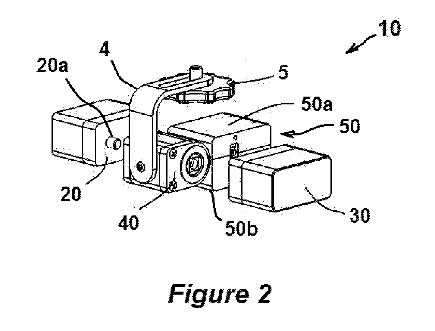
[0025]While the invention is described in conjunction with the accompanying drawings, the drawings are for purposes of illustrating exemplary embodiments of the invention and are not to be construed as limiting the invention to such embodiments. It is understood that the invention may take form in various components and arrangement of components beyond those provided in the drawings and associated description. Within the drawings, like reference numerals denote like elements. The term “device” is frequently used in describing an imaging object mounted to the apparatus which means a camera, video recorder, camera phone, laser, lens, and sensors.

[0026]The automatic stabilization apparatus is comprised of several subassemblies, which combined to provide device control while giving special consideration to the physical size, visual obtrusiveness, adaptability to different devices, and cost of manufacturability. In other words, an automatic stabilization apparatus is small, light, attrac...


PUM


Abstract

An automated stabilizing apparatus includes a bracket to mount an image device such as a camcorder or camera phone and a differential gear assembly connected to the bracket; a first and second drive system, consists of a bidirectional DC motor, an encoder, and a gear train, having an output shaft couples to the differential gear assembly; and an electronic enclosure houses controls elements that include a microcontroller, motor drivers, and sensors in communication with the drive systems to maintain the bracket and image device steady over a wide range of positions.

Description

BACKGROUND OF THE INVENTION[0001]When shooting videos using an imaging device such as a camera phone or a light camcorder, hand and body movements tend to transmit to the camera thus producing shaky videos. There are imaging devices with features such as built-in image stabilization to improve the video quality, and these features utilize either a software image stabilization technique to smooth minor jitters in the video or an optical stabilization technique where a lens is physically shifted inside the camera to counter the movements of the camera body. In general, these techniques work well for small vibrations measured within a few degrees of movement, however, larger rotating movements of the camera associated with walking or running requires other external devices to stabilize the camera.[0002]For many years, a device such as a steadycam uses a counterweight to balance the camera such that the camera and the counterweigh pivot about a swivel joint located somewhere in between....

Claims


Application Information

Patent Timeline
Patent Type & Authority Applications(United States)
IPC IPC(8): G03B17/56
CPCG03B17/561F16M11/048F16M11/10F16M11/18F16M11/2021F16M13/04G02B27/644G03B17/563G03B2217/005G03B2217/007F16M13/00
Inventor HOANG, CHI KHAI
Owner HOANG CHI KHAI
Why Eureka
Try Eureka