Method and System for Controller Transition

a controller and controller technology, applied in the field of controller transition, can solve the problems of not being able to shut down the emergency system, involving large costs, etc., and achieve the effects of avoiding damage to the first controller, reliable system operation, and avoiding damage to the controller

Active Publication Date: 2015-03-12
SIEMENS ENERGY AS
View PDF4 Cites 7 Cited by
  • Summary
  • Abstract
  • Description
  • Claims
  • Application Information

AI Technical Summary

Benefits of technology

[0043]The first controllable input block may avoid that an input signal supplied to the first input terminal may be transferred to the first internal input port for avoiding damage of the first controller. Further, the first controllable output block may avoid damage of the first controller when the output line is disconnected from the first controller or when a potential at the first output terminal is in an undefined condition. The same may apply to the second controllable input block and to the second controllable output block of the second controller.
[0044]Thereby, damage of the controller may be avoided, thus ensuring reliable operation of the system.

Problems solved by technology

In particular, it may not be possible to shut down the emergency system since shutting down the emergency system may involve extensive costs.

Method used


Image

  • Method and System for Controller Transition
  • Method and System for Controller Transition

Examples


Embodiment Construction

[0051]The illustration in the drawing is in schematic form.

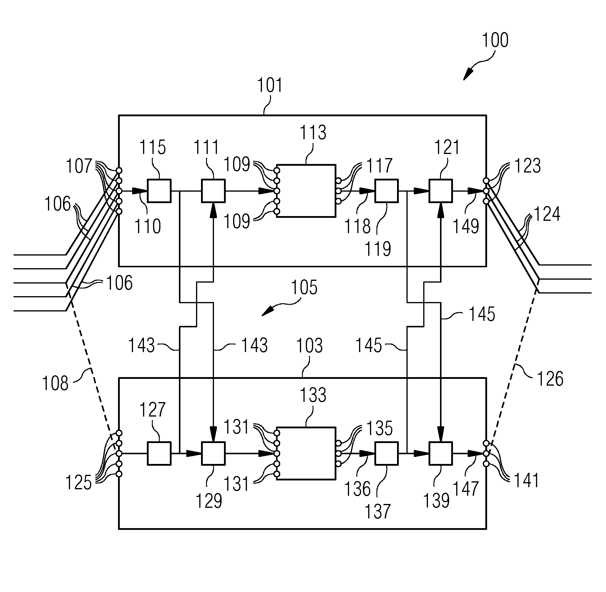
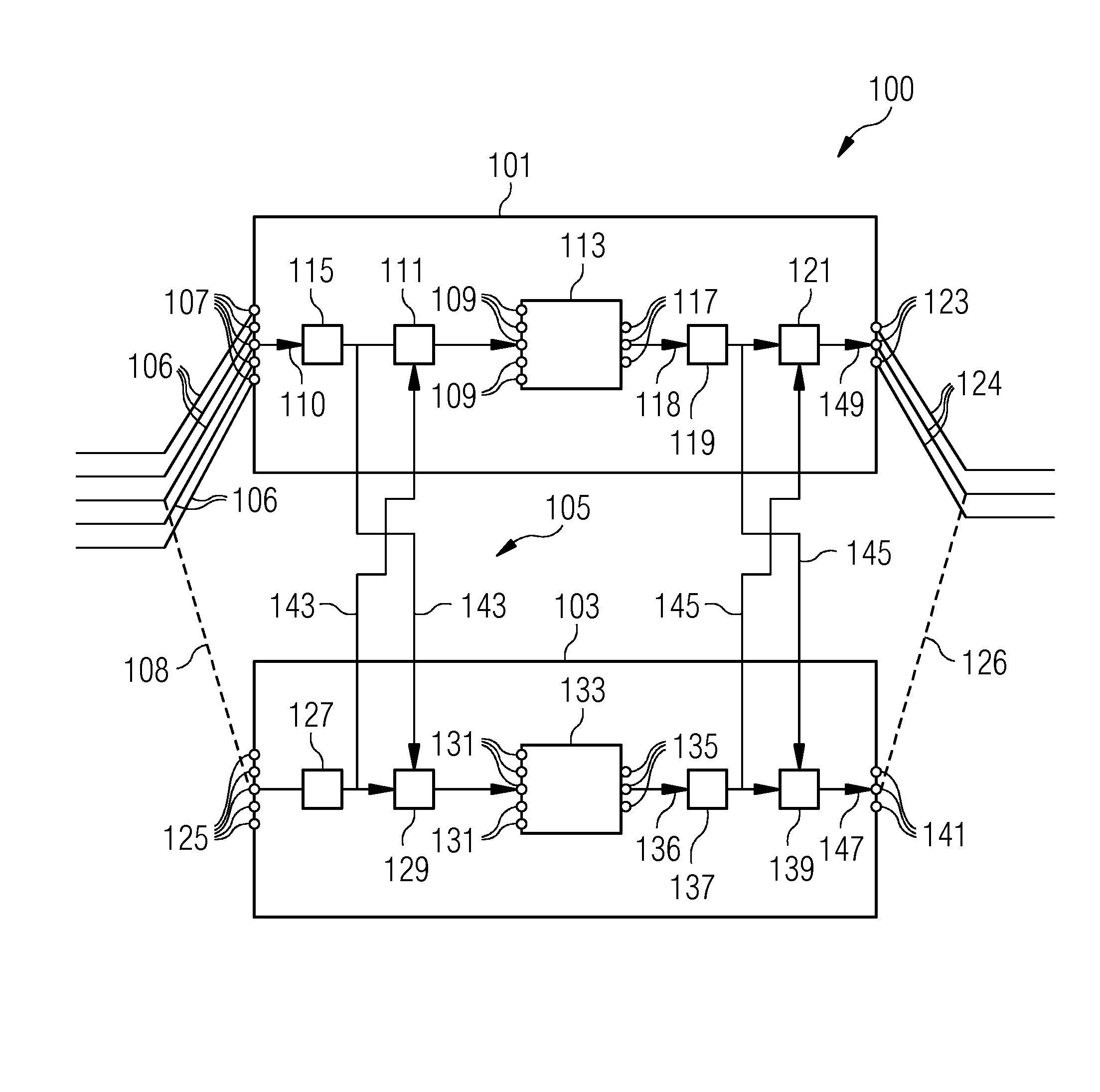
[0052]The system 100 comprises the first controller 101, the second controller 103 and a communication system 105 for communicatively coupling the first controller 101 and the second controller 103.

[0053]The first controller 101 has at least one first input terminal 107, here exemplarily represented by five first input terminals 107, providing a first input signal 110. Further, the first controller 101 comprises a first internal input port 109 again exemplarily represented by five input ports 109 corresponding to the five first input terminals 107. Further, the first controller comprises at least one first input OR-gate 111, which is arranged between the first input terminal 107 and the first internal input port 109.

[0054]For clarity only one signal path between the first input terminal 107 and the first internal input port 109 is illustrated in the FIGURE, although each of the at least one first input terminal 107 comprises...


PUM


Abstract

It is described a method for transition of control from a first controller (101) to a second controller (103), the method comprising: communicatively coupling (143, 145) the first controller and the second controller, such that at least one static digital input signal (110) received by one controller (101) is mutually provided to the respective other controller (103) and such that at least one static digital output signal (118) generated by one controller (101) is mutually provided to the respective other controller (103); disconnecting at least one output line (124) from the first controller (101); connecting the at least one output line (126) to the second controller (103); supplying at least one output signal (147) to the at least one output line (126), wherein the at least one output signal (147) is obtained by performing a logical OR, in particular using an OR-gate, to at least one first output signal (118) generated by the first controller (101) and at least one second output signal (136) generated by the second controller (103), the method further comprising before disconnecting at least one output line (124) from the first controller (101): supplying a logical high signal to the output line by an external voltage source, if the first output signal (118) is a logical high signal or if the output line is at a logical high state during normal operation.

Description

FIELD OF INVENTION[0001]The present invention relates to a method for transition of control between two controllers and to a system for transition of control between two controllers, wherein the controllers are in particular provided for controlling actuators for operating of a gas and / or fire emergency equipment, in particular during oil exploration.ART BACKGROUND[0002]For production of oil and / or gas, in particular using an offshore oil or gas platform, it may be necessary to provide equipment for taking measures in an emergency case, such as a fire emergency case or a gas release emergency case. In particular, one or more actuators, such as pumps may be needed to be operated in order to fight the gas and / or fire emergency situation.[0003]The emergency equipment may be controlled by a controller receiving one or more input signals, such as input signals derived from one or more sensors or derived from manual input of a maintenance personnel.[0004]From time to time the controller(s...

Claims


Application Information

Patent Timeline
Patent Type & Authority Applications(United States)
IPC IPC(8): G05B9/03G05B19/05
CPCG05B9/03G05B2219/14014G05B19/054G05B19/0428G05B2219/25471
Inventor GONZALEZ-MENDOZA, DAGOBERTOSVEEN, ARNT OLAV
Owner SIEMENS ENERGY AS
Why Eureka
Try Eureka