Piston pump

a piston pump and hand-operated technology, which is applied in the direction of couplings, steering rudders, liquid fuel engines, etc., can solve the problems of relatively high cost, large production cost, and inability to manufacture the valve plate, etc., to achieve easy mounting and assembly of various parts, low degree of accuracy, and facilitate the effect of mounting and assembly

Active Publication Date: 2015-03-19
ULTRAFLEX
View PDF2 Cites 3 Cited by
  • Summary
  • Abstract
  • Description
  • Claims
  • Application Information

AI Technical Summary

Benefits of technology

[0053]This improvement facilitates mounting and assembly of the various parts of the pump.
[0054]Particularly, the above described characteristics will obviously impart modular features to the pump of the invention, allowing easy mounting and assembly of the various parts.
[0055]Also, the concept that adds novelty and inventive step to the pump of the present invention, and makes it particularly advantageous as compared with prior art pumps due to the provision of floating or semi-floating parts which might compensate for a low degree of accuracy in the construction of each part, thereby affording considerable savings.

Problems solved by technology

Therefore, those pumps are relatively complex and expensive, as they are composed of relatively complex parts, having complex conduits for the passage of the pressurized fluid.
The manufacture of the valve plate, with the holes and ports for the passage of pressurized fluids, in a single construction piece, i.e. in one piece with the base, is generally relatively expensive both in terms of fabrication of the blank and for the required drilling of the passages for the pressurized fluid, as well as for additional finishing steps.
A valve plate integrated with the base has a very high cost.
Those holes and these recesses are also not easily formed, when the base is made of one piece with the valve plate.
Due to these requirements, a high degree of accuracy is required for construction and assembly of the above mentioned parts, which will strongly impinge on manufacturing and maintenance costs for the pumps.
Therefore, there exists a yet unfulfilled need in the art for a piston pump that can resolve the above described drawbacks of prior art pumps, particularly a piston pump that can provide the same efficiency as prior art pumps while affording low manufacturing costs and easy construction.

Method used


Image

  • Piston pump
  • Piston pump
  • Piston pump

Examples


Embodiment Construction

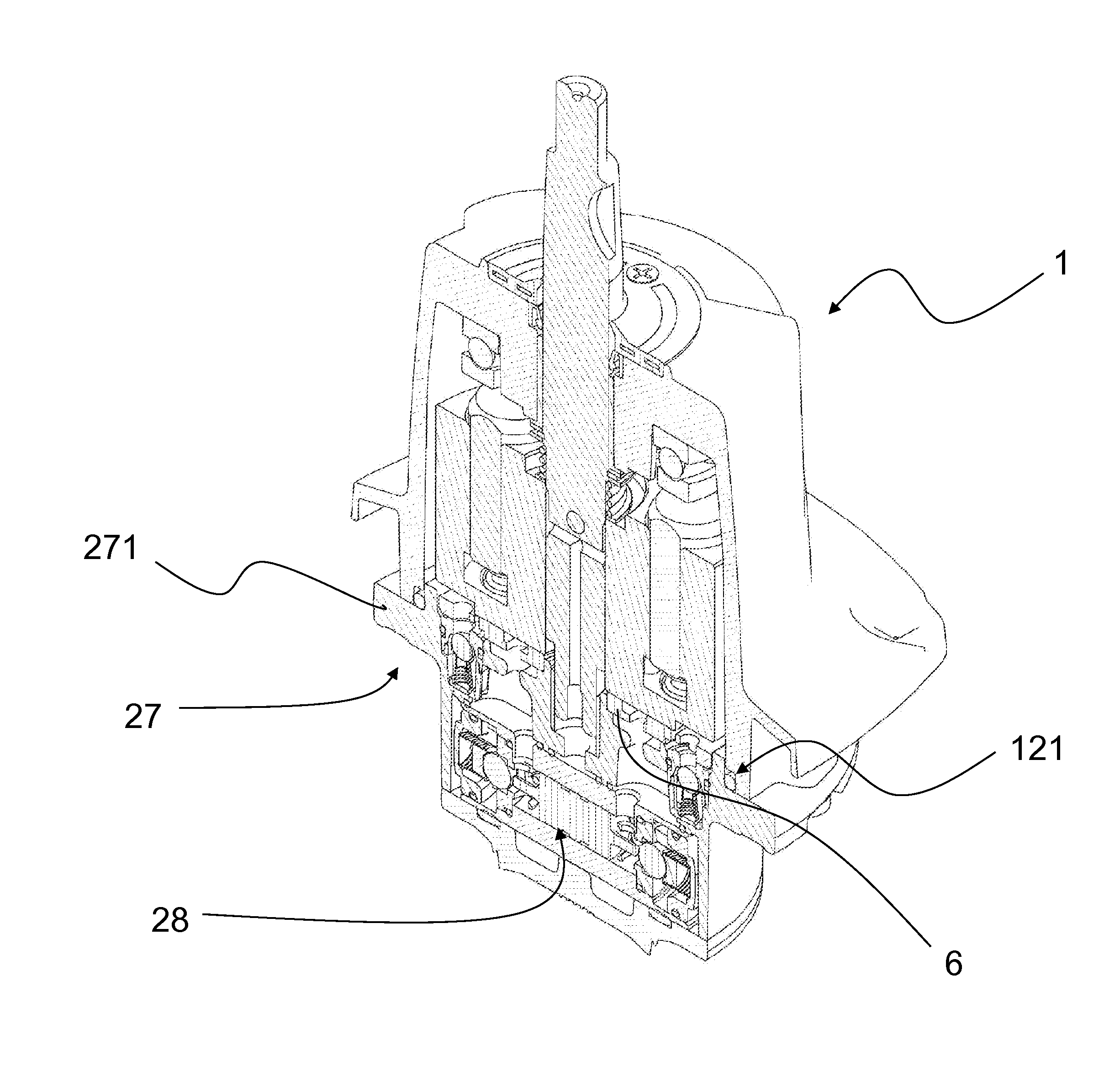
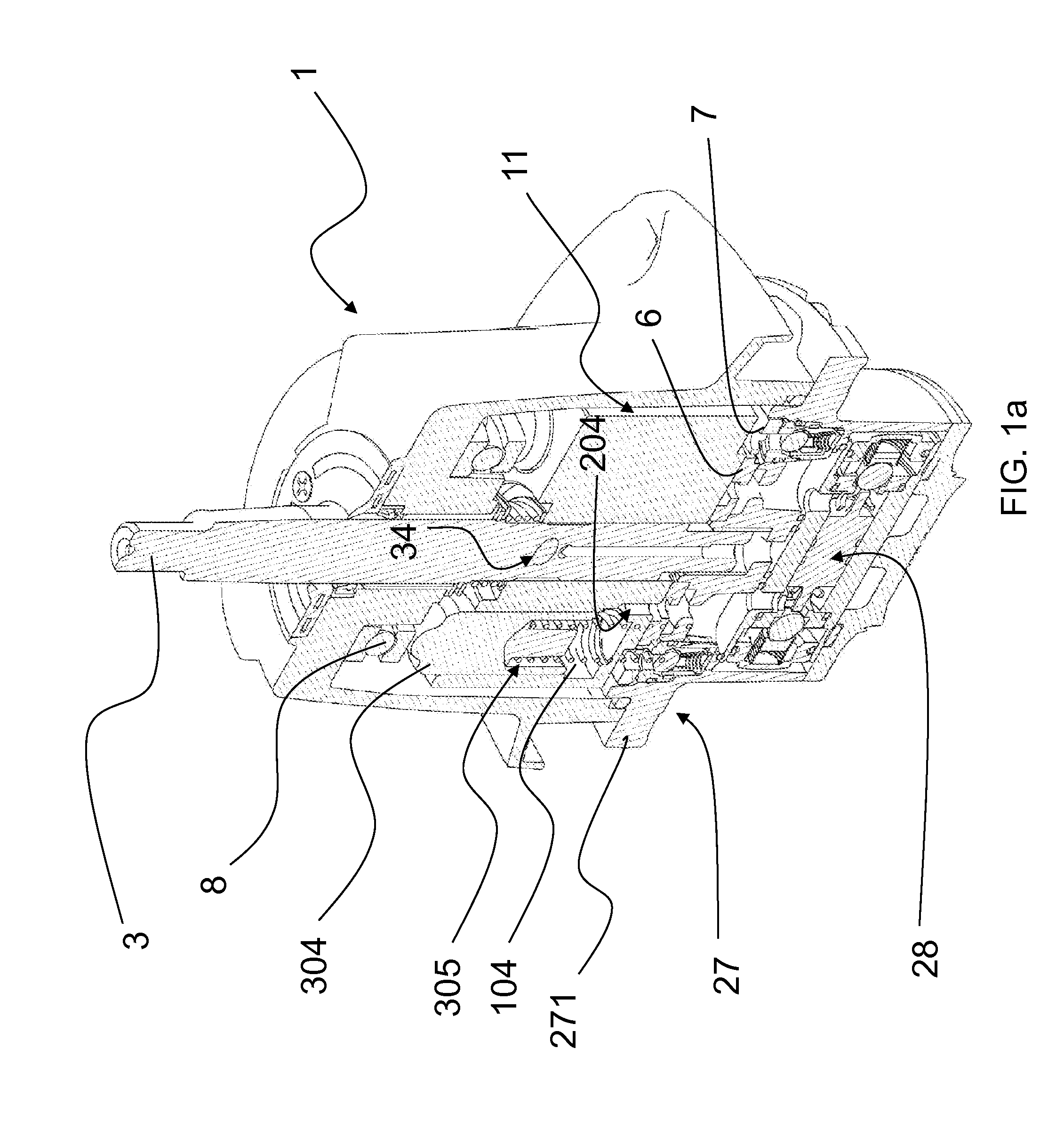
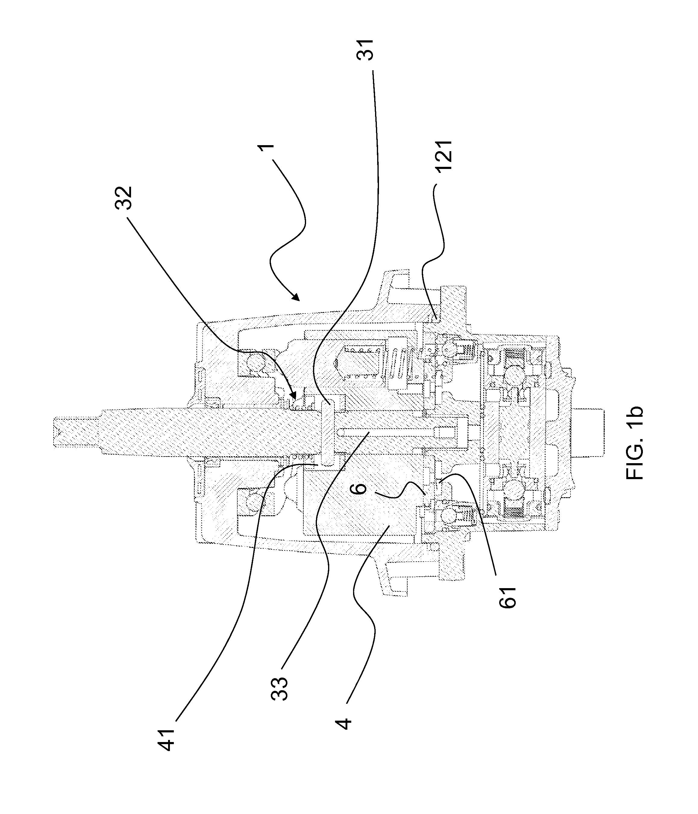
[0069]FIGS. 1a-1d show a hand-operated piston pump according to the present invention, which is particularly suited for directional control of a watercraft, a boat or the like.

[0070]The illustrated pump comprises a drive shaft 3, which is rotatably mounted in a housing case 1, a rotor 4 being mounted in the housing case 1.

[0071]The rotor 4 is rotationally integral with the drive shaft 3 and has a plurality of axial compression chambers 104 formed in the body of the rotor 4, which surround the drive shaft 3.

[0072]A piston 304 is axially and slidably housed in each compression chamber 104 and is biased by elastic means 305, with one end projecting out of one end side of the corresponding compression chamber 104 against a cam track 8 consisting of an annular plate inclined with respect to the axis of rotation of the rotor 4.

[0073]The pump further comprises a fluid reservoir 11 in the housing case 1, as well as a valve plate 6 located downstream from the rotor 4.

[0074]The valve plate 6 ...


PUM


Abstract

A hand-operated piston pump includes a drive shaft and a rotor mounted in a housing case, the rotor having axial compression chambers, a piston biased by an elastic member sliding in each compression chamber and having a projecting end that engages a cam track; a fluid reservoir in the housing case; a valve plate downstream of the rotor having conduits for a pressurized fluid that communicate with conduits in walls of the compression chambers, the valve plate being non-rotatably mounted below the housing case and communicating with conduits that carry the pressurized fluid to and from a consuming unit through an interposed check valve inserted in a corresponding valve body, the valve body having an upper flange with fluid supply and return channels communicating with the fluid conduits of the valve plate. The valve plate floats relative to the upper flange and is separated therefrom by a separating member.

Description

FIELD OF THE INVENTION[0001]The present invention relates to a hand-operated piston pump, particularly for directional control of watercraft, boats or the like.[0002]The pump comprises a drive shaft, which is rotatably mounted in a housing case, and a rotor, which is mounted in the housing case and is rotationally integral with the drive shaft, said rotor having a plurality of axial compression chambers formed in the body of the rotor.[0003]The axial compression chambers surround the drive shaft, a piston being axially slidably housed in each compression chamber and biased by elastic means, with one end projecting out of one end side of the corresponding compression chamber against a cam track comprising an annular plate inclined with respect to the axis of rotation of the rotor.[0004]A fluid reservoir is also provided in the housing case.[0005]The pump further comprises a valve plate, which is located downstream from the rotor, in the direction of the fluid, particularly in the flo...

Claims


Application Information

Patent Timeline
Patent Type & Authority Applications(United States)
IPC IPC(8): B63H25/30F04B1/22F04B1/20B63H25/22
CPCB63H25/30F04B1/2042F04B1/22B63H25/22F04B1/20F04B9/14F01B3/0032F04B1/2007
Inventor GAI, MARCELLAPAGANI, ENRICOMILANESE, ANDREA
Owner ULTRAFLEX
Why Eureka
Try Eureka