Separator and method for separating liquid droplets from an aerosol

Active Publication Date: 2015-03-19
ELRINGKLINGER AG
View PDF11 Cites 20 Cited by
  • Summary
  • Abstract
  • Description
  • Claims
  • Application Information

AI Technical Summary

Benefits of technology

[0021]Regarding the separation performance of a separator constructed in accordance with the invention, considerable advantages are gained if the channel height (measured in a direction of the rotor axis) is substantially larger than the channel width and is in particular approximately a multiple of the channel width. In this connection, the following is to be pointed out: Due to the effect of the Coriolis force, a channel has induced therein a secondary flow in the gas flowing therethrough, said secondary flow (when viewed in a section taken through the channel in a direction perpendicular to the channel axis) consisting of at least two vortices lying side-by-side between the channel wall surfaces bounding the channel width; however, the effects of this secondary velocity on the separation performance of the separator are significant only in the lateral peripheral regions of the channel, i.e. in the vicinity of the channel wall surfaces bounding the channel width, because it is there that the highest flow velocities of the secondary flow occur. Since this secondary velocity has a negative effect on the separation efficiency, it is desirable for the channel cross-section to be configured such that the ratio between the channel cross-sectional areas of hi

Problems solved by technology

However, the relatively high pressure loss in the gas stream of the blow-by gases that is caused by the presence of such passive separators may be disadvantageous and the separation efficiency of such passive systems on material in the ultra-fine droplet range with droplets sized approximately 0.7 μm or less is in need of improvement; any improvement in this regard has heretofore required the use of powered separators, in particular separators of the kind as are a

Method used


Image

  • Separator and method for separating liquid droplets from an aerosol
  • Separator and method for separating liquid droplets from an aerosol
  • Separator and method for separating liquid droplets from an aerosol

Examples


Example

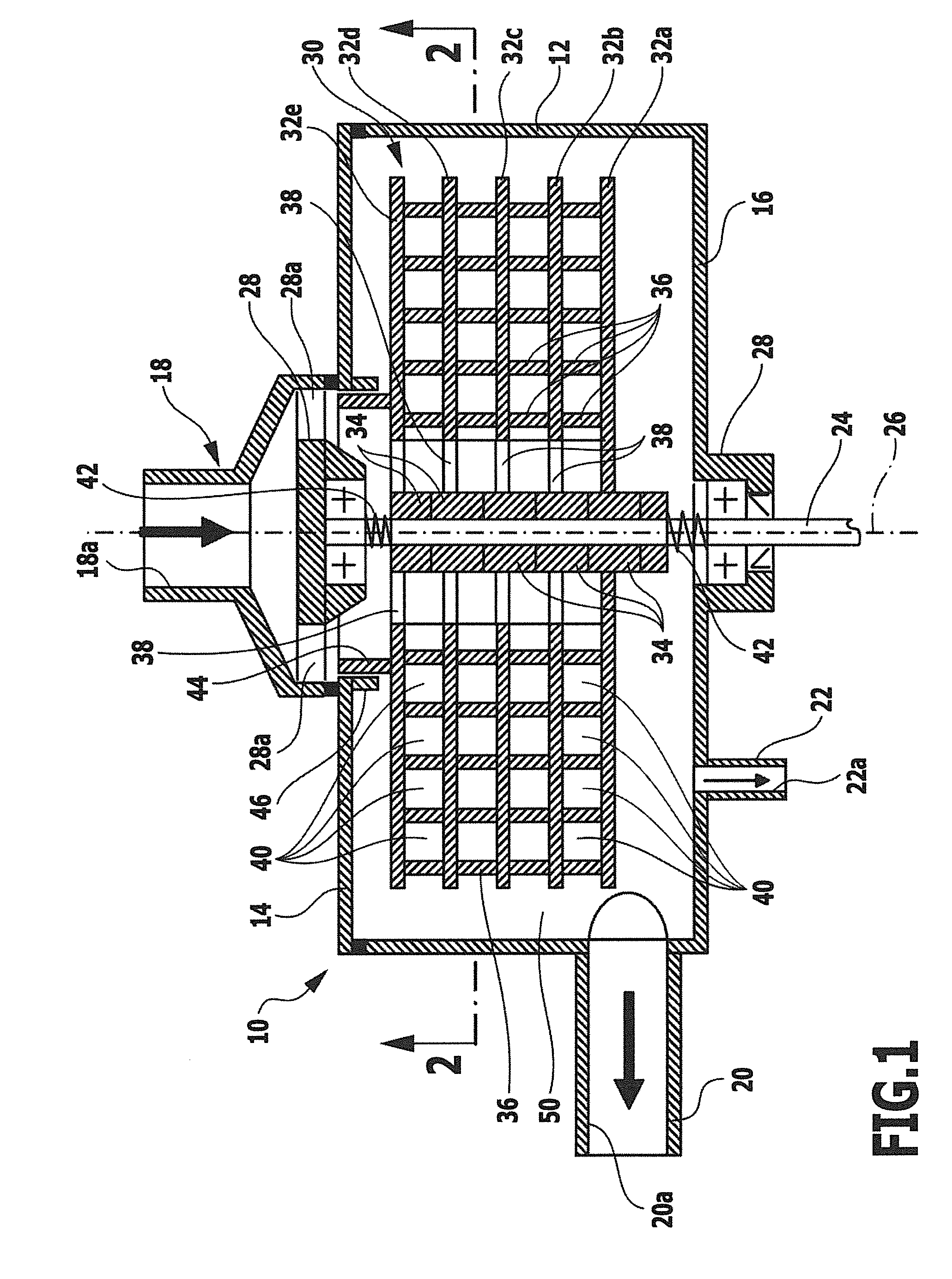
[0034]The separator illustrated in FIG. 1 has a multi-part housing 10 comprising a circumferential wall 12, an upper and a lower end wall 14 and 16 respectively and a hood-like inlet connection 18, an outlet connection 20 and a drain connection 22, wherein the individual housing parts are connected together in a gas and liquid-tight manner, preferably by welding. In the embodiment illustrated, the inlet connection 18 forms a dirty gas inlet 18a, i.e. an inlet for the gas to be cleaned, the outlet connection 20 forms a clean gas outlet 20a for the cleaned gas and the drain connection 22 forms a liquid outlet 22a for liquid separated from the dirty gas by the separator.

[0035]However, the functions of the connections 18 and 20 may also be reversed, i.e. the connection 20 could form a dirty gas inlet and the connection 18 could form a clean gas outlet, in those instances where the gas to be cleaned is intended not to flow radially from inside out but from outside in through the rotor of...


PUM

PropertyMeasurementUnit
Widthaaaaaaaaaa
Widthaaaaaaaaaa
Lengthaaaaaaaaaa

Abstract

A separator for separating liquid droplets from an aerosol is provided, including a rotor arranged in a housing and including a plurality of parallel disks, a dirty gas inlet, a clean gas outlet, and an annular space between the rotor's circumference and the housing, wherein adjacent disks form an interspace therebetween, the radially outer area of the interspace opening into the annular space, and wherein one of the dirty gas inlet and the clean gas outlet communicates with the annular space and the other communicates with radially inner areas of the interspaces. The disks have flat disk bodies perpendicular to the rotor axis, and between adjacent disk bodies, there are a plurality of adjacent channels allowing passage of the gas to be cleaned. Each channel is curved and the radially outer channel wall forms an impaction and separation surface for the liquid droplets.

Description

CROSS-REFERENCE TO RELATED APPLICATIONS[0001]The present application is a continuation of international application number PCT / EP2013 / 060207, filed on May 16, 2013, which claims priority to German patent application number 10 2012 104 598.4, filed May 29, 2012, the entire specification of both being incorporated herein by reference.BACKGROUND OF THE INVENTION[0002]The invention relates to a separator for separating liquid droplets from an aerosol, and relates in particular to an oil separator for the crankcase ventilation gases of a reciprocating internal combustion engine, comprising a rotor arranged in a stationary housing and capable of being driven in rotation about a rotor axis, said rotor comprising a plurality of disks which are concentric with the rotor axis and are arranged parallel to one another, said disks together forming a stack of disks capable of being driven in rotation about the rotor axis and being arranged at in particular equal distances relative to one another ...

Claims


Application Information

Patent Timeline
IPC IPC(8): F01M13/04B01D45/14
CPCF01M13/04F01M2013/0422B01D45/14B04B5/12B04B2005/125B04B7/12C04B41/009C04B38/0006
Inventor GORBACH, GABRIELECOOLENS, HOLGERPIESCHE, MANFREDJUNKER, MALTE
Owner ELRINGKLINGER AG
Why Eureka
Try Eureka