
Charged particle beam apparatus, specimen observation system and operation program

a particle beam apparatus and charge technology, applied in the direction of material analysis using wave/particle radiation, instruments, nuclear engineering, etc., can solve the problems of novice users having a hard time improving their skills, and users having difficulty in knowing what kind of influence the electron microscope observation condition has on the captured image, etc., to achieve the effect of easy recognition of the difference between imaging results

Active Publication Date: 2015-03-19
HITACHI HIGH-TECH CORP
View PDF8 Cites 3 Cited by
  • Summary
  • Abstract
  • Description
  • Claims
  • Application Information

AI Technical Summary

Benefits of technology

The invention helps to easily identify differences in imaging results caused by different observation conditions.

Problems solved by technology

For this reason, when a novice user operating the electron microscope, the user has difficulty in knowing what kind of influence the electron microscope observation condition has on a captured image.
As a result, there is a problem that the novice user has a hard time improving his / her skills.

Method used


Image

  • Charged particle beam apparatus, specimen observation system and operation program
  • Charged particle beam apparatus, specimen observation system and operation program
  • Charged particle beam apparatus, specimen observation system and operation program

Examples


Embodiment Construction

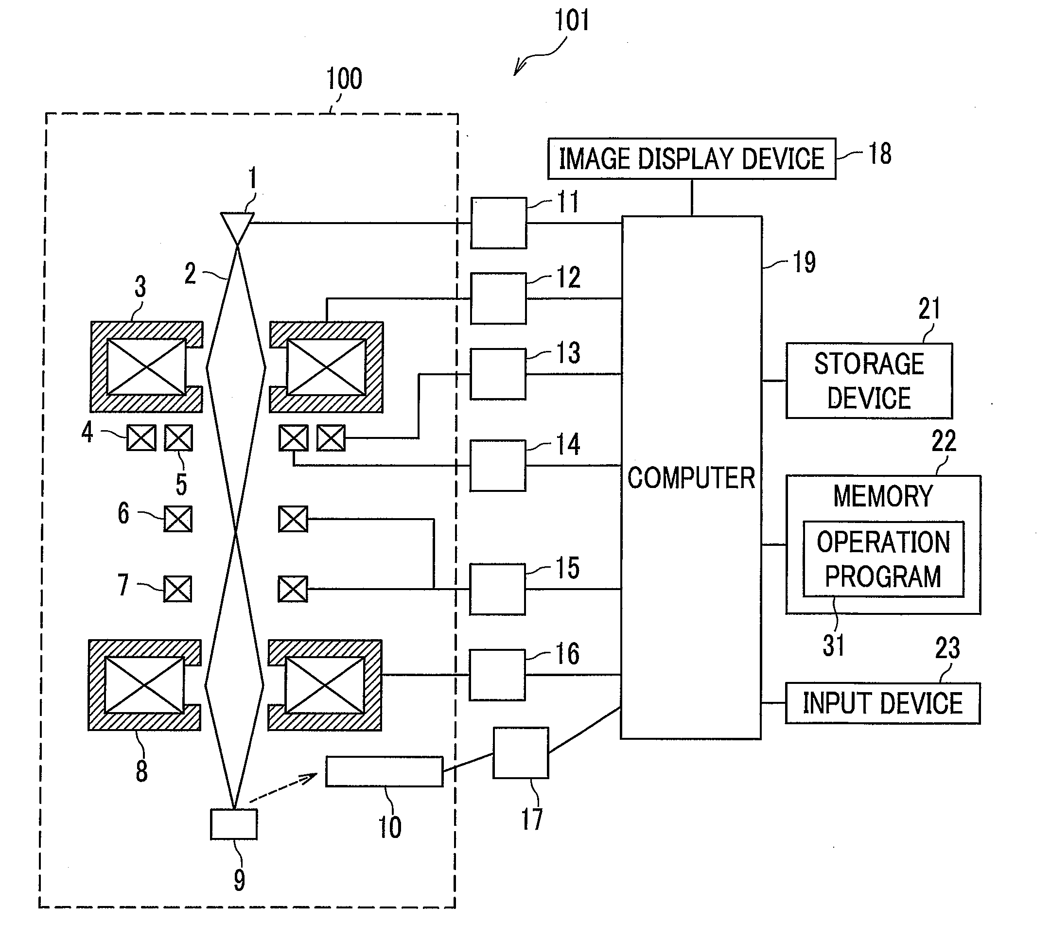
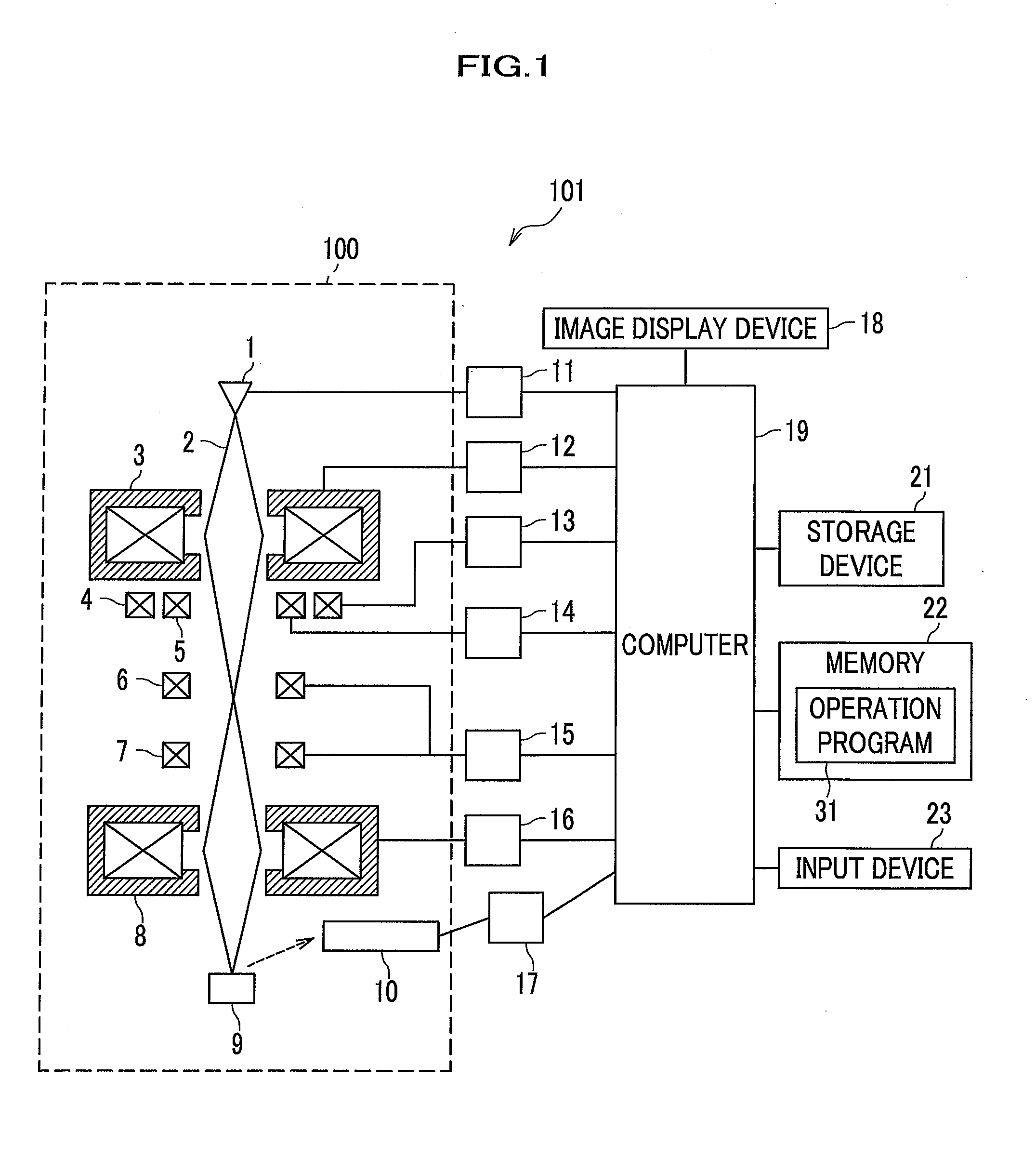
[0049]Next, a mode for carrying out the present invention (hereinafter referred to as the “embodiment”) is described in detail with reference to the appropriate drawings. Note that, in the drawings, the same constituent components are denoted by the same reference numerals, and description thereof is omitted.

[0050]Note that the embodiment discloses a charged particle beam apparatus including a processing unit configured to display, on an image display unit in an image display device, observation target setting buttons for changing an observation condition for a specimen which includes a combination of parameter setting values of the charged particle beam apparatus. The processing unit is configured for displaying a highlighted image, in which an image change due to a change of the observation condition is highlighted, on or near each of the observation target setting buttons.

[0051]The embodiment also discloses that respective one of the observation target setting buttons and corresp...


PUM


Abstract

For a novice user to easily recognize a difference between imaging results caused by a difference between observation conditions, a computer has an operation screen display observation target setting buttons for changing an observation condition for a specimen including a combination of parameter setting values of a charged particle beam apparatus. The processing unit has the operation screen display a radar chart including a characteristic, indicated by three or more incompatible items, of an observation condition for each of the observation target setting buttons. The radar chart indicates at least items of high resolution, emphasis on surface structure and emphasis on material difference.

Description

TECHNICAL FIELD[0001]The present invention relates to techniques of a charged particle beam apparatus, a specimen observation system and an operation program.BACKGROUND ART[0002]Setting of a combination of parameter setting values (hereinafter referred to as an observation condition) which are setting values of parameters in operation of a scanning electron microscope (hereinafter referred to as the electron microscope) largely relies on experience. For this reason, when a novice user operating the electron microscope, the user has difficulty in knowing what kind of influence the electron microscope observation condition has on a captured image. As a result, there is a problem that the novice user has a hard time improving his / her skills.[0003]To counter such a problem, in techniques described in Patent Documents 1 and 2, capturings are performed under two or more combinations of simple observation conditions prior to main capturing. Then, two or more simple observation images thus ...

Claims


Application Information

Patent Timeline
Patent Type & Authority Applications(United States)
IPC IPC(8): H01J37/22H01J37/28
CPCH01J37/222H01J2237/2806H01J37/28H01J37/265
Inventor KONISHI, YAYOISATO, MITSUGUTAKANO, MASAKITAMAYAMA, SHOTARONISHIMURA, MASAKOWATANABE, SHUNYAKONOMI, MAMI
Owner HITACHI HIGH-TECH CORP
Learn More