Stator for rotating electric machine

a technology of rotating electric machines and rotating shafts, which is applied in the direction of dynamo-electric components, ac commutators, dynamo-electric machines, etc., to achieve the effect of preventing the axial length of the coil end portion from increasing and preventing the circulating curren

Active Publication Date: 2015-03-19
DENSO CORP
View PDF3 Cites 51 Cited by
  • Summary
  • Abstract
  • Description
  • Claims
  • Application Information

AI Technical Summary

Benefits of technology

[0016]In the stator configured as above, for each pair of the circumferentially adjacent slots for the phase winding, the slot-received portion inserted in an m-th layer (m being a positive integer) of each slot of the pair of circumferentially adjacent slots is electrically connected to the slot-received portion inserted in an (m+1)-th layer of one of slots of an adjacent pair of circumferentially adjacent slots. This can prevent axial lengths of the coil end portions from increasing.
[0017]Each of the phase windings is a parallel connection of 4×n (n being a positive integer) parallel windings. In a portion of the stator winding at an axial coil end of the stator winding opposite a portion of the stator winding formed of a plurality of bent portions, each of the parallel windings of each of the phase windings (41U, 41V, 41W) revolves circumferentially while alternating the first and second slot groups in the circumferential direction through a combination of five and seven slot pitch based switchings. This allows for striking a balance between the parallel windings, thereby completely preventing circulating current from occurring between the parallel windings.

Problems solved by technology

Five slot pitch based switching and seven slot pitch based switching are provided so that the phase winding can switch between the first and second slot groups, which, however, may give rise to a disadvantage that an outer conductor segment 72A inserted in the first and fourth layers of the slots that are five slots away from each other straddles the normal inner conductor segment 71 inserted in the second and third layers of the slots that are six slots away from each other.

Method used


Image

  • Stator for rotating electric machine
  • Stator for rotating electric machine
  • Stator for rotating electric machine

Examples


first embodiment

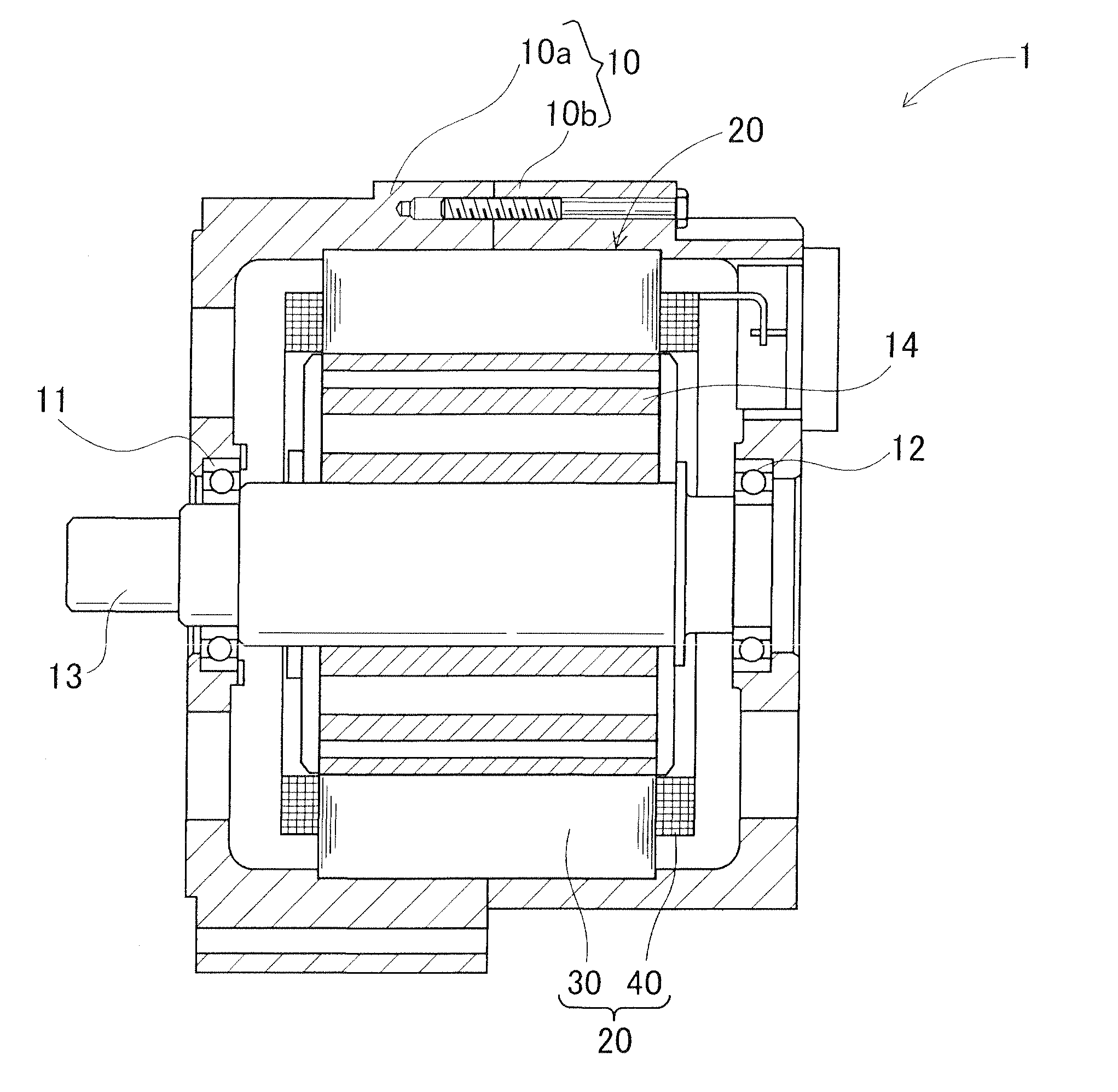
[0041]A rotating electric machine 1 incorporating therein a stator 20 in accordance with a first embodiment of the present invention may be used as a vehicle electrical motor. As shown in FIG. 1, the rotating electric machine 1 includes a housing 10 formed by joining openings of a pair of housing members 10a and 10b both shaped like a dosed-end cylinder (referring here to a cylinder closed at one end), opening to opening, a rotor 14 secured to a rotary shaft 13 rotatably supported by the housing 10 via bearings 11 and 12, and a stator 20 positioned to encompass the rotor 14 within the housing 10 and fixed to the housing 10.

[0042]The rotor 14 has a plurality of poles that are arranged around the outer circumference of the rotator 14 opposite the inner circumference of the stator 20, circumferentially spaced a predetermined distance apart from each other and circumferentially alternating in polarity. The plurality of poles are formed by a plurality of permanent magnets embedded at pre...

second embodiment

[0078]A stator of a rotating electric machine (not shown) in accordance with a second embodiment of the present invention is similar in basic configuration as in the first embodiment except that the winding specifications for the phase windings 41U, 41, V41 forming the stator winding 40 are different from those of the first embodiment. Therefore, only different features and important features will be described in the following description.

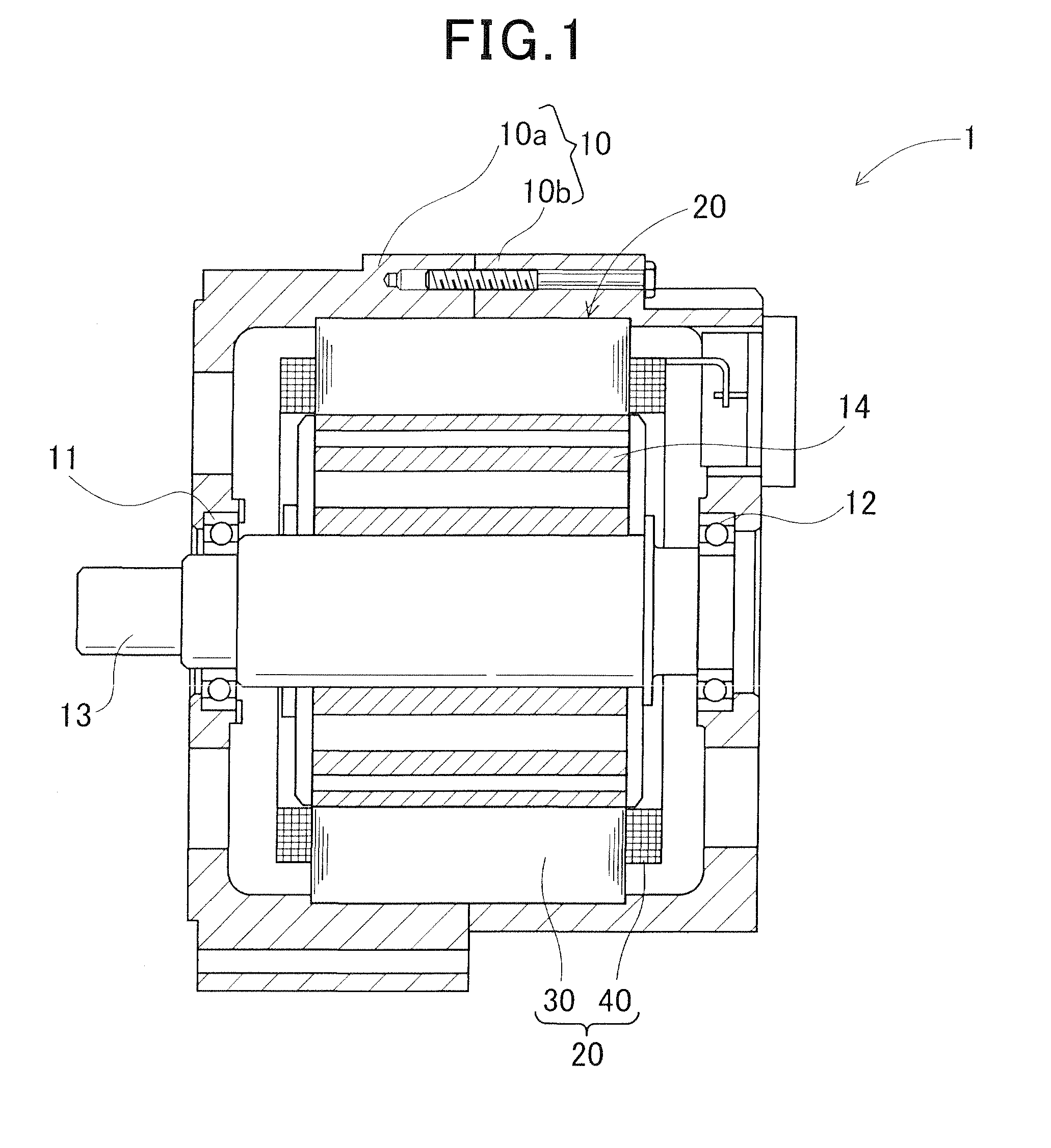
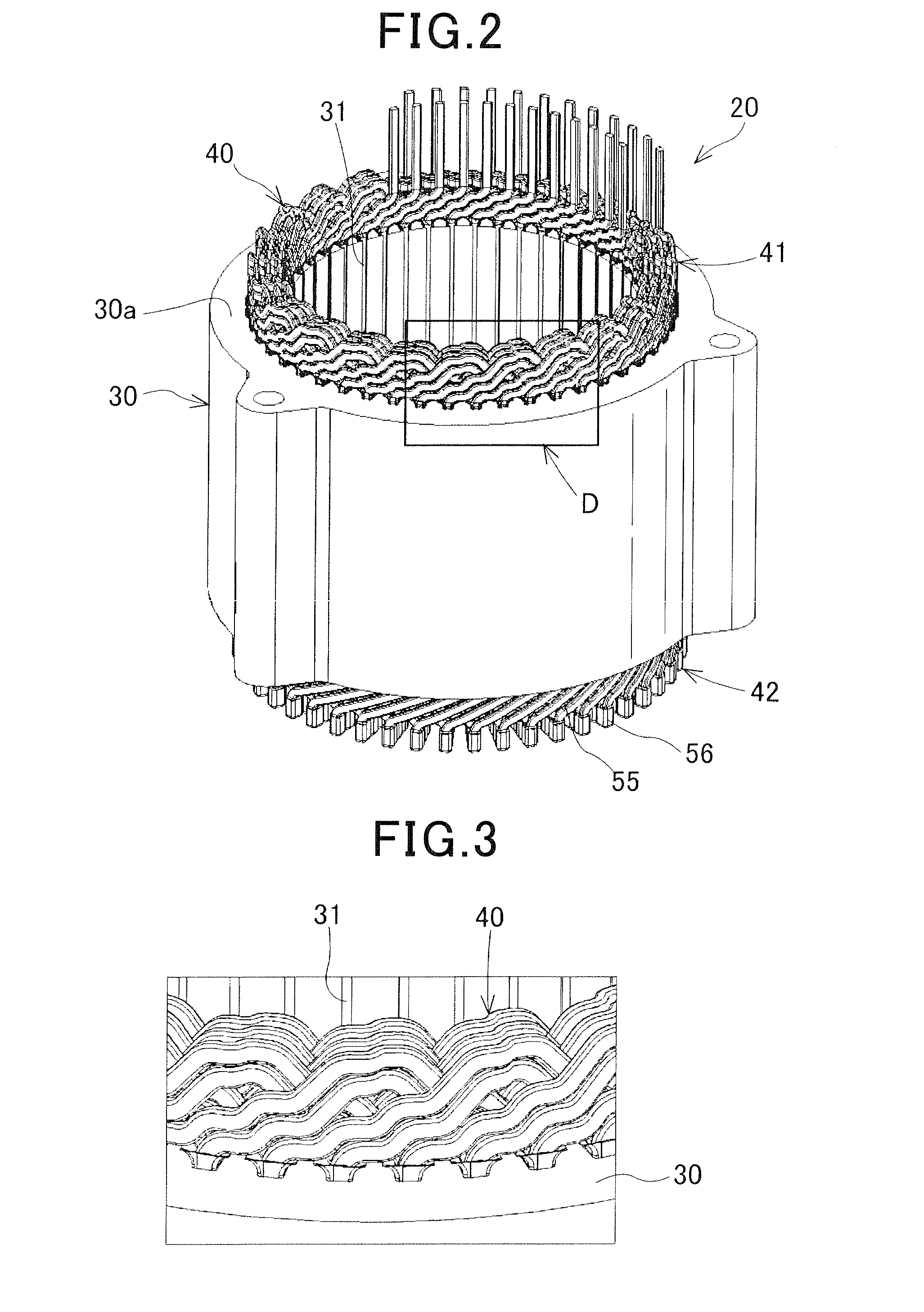
[0079]In the stator winding 40 of the second embodiment, as in the first embodiment, one end of a U-phase winding 41U that is a parallel connection of four parallel windings U1-U4, one end of a V-phase winding 41V that is a parallel connection of four parallel windings V1-V4, and one end of a W-phase winding 41W that is a parallel connection of four parallel windings W1-W4 are electrically star connected at a neutral point (see FIG. 6). The stator winding 40 is formed of a plurality of U-shaped conductor segments 50 inserted in a plurality of slots...


PUM


Abstract

A stator core with a plurality of slots circumferentially arranged therearound has a stator winding including three (UVW) phase windings, each phase winding having 4n parallel windings. The stator winding is formed of U-shaped conductor segments inserted in the slots from one axial end, a pair of open end portions of each conductor segment extending axially from of the stator core and being bent toward circumferentially opposite directions, the bent portions being star connected together. The plurality of slots have, for each phase winding, pairs of circumferentially adjacent slots, each slot having an even number of slot-received portions of the phase winding radially aligned in a column, and for each circumferential slot pairs, the slot-received portion in an m-th layer of each slot of the pair is electrically connected to the portion inserted in an (m+1)-th layer of a slot of a circumferentially adjacent slot.

Description

CROSS-REFERENCE TO RELATED APPLICATION[0001]This application is based on and claims the benefit of priority from earlier Japanese Patent Applications No. 2013-192933 filed Sep. 18, 2013 and No. 2014-156229 filed Jul. 31, 2014, the descriptions of which are incorporated herein by reference.BACKGROUND[0002]1. Technical Field[0003]The present invention relates to a stator for a rotating electric machine mounted in a vehicle or the like and used as an electrical motor or a generator.[0004]2. Related Art[0005]A rotating electric machine to be mounted in a vehicle is generally known that includes a rotor, a stator core including a plurality of slots radially opposing the rotor and arranged in a circumferential direction of the core, and a stator having a stator winding formed of a plurality of phase windings wound through the slots of the stator core.[0006]Japanese Patent Application Laid-Open Publication No. 2005-110361 discloses techniques for an armature (or the stator) for the rotatin...

Claims


Application Information

Patent Timeline
Patent Type & Authority Applications(United States)
IPC IPC(8): H02K3/28H02K3/12
CPCH02K3/12H02K3/28
Inventor TAMURA, AKITO
Owner DENSO CORP
Why Eureka
Try Eureka