Unlock instant, AI-driven research and patent intelligence for your innovation.

Projection system, image processing device, and projection method

Active Publication Date: 2015-03-19
RICOH KK
View PDF7 Cites 49 Cited by
  • Summary
  • Abstract
  • Description
  • Claims
  • Application Information

AI Technical Summary

Benefits of technology

The present invention provides a projection system for projecting an image onto a projection body by multiple projection devices. The system includes an image preparation unit that prepares multiple imaging images for calibration, a grid point extraction unit that extracts a set of grid points that indicate distortion in a projection image for each calibration image, a grid point transformation unit that performs a transformation between the multiple images to ensure the same grid points are in a common coordinate system, a grid point synthesis unit that produces a set of grid points that are common to the projection devices, and a correction coefficient calculation unit that calculates a correction coefficient for the projection devices based on the transformed and synthesized grid points. This system ensures accurate and precise projection of images onto the projection body.

Problems solved by technology

Therefore, it is not sufficient because a mechanism such an a tripod mount is needed and convenience is lowered.
Furthermore, as the number of projectors are increased, it may be difficult to image in projection ranges of all the projectors inside an angle of view at once.
Herein, in a case where patterns from projectors are combined, it is difficult to separate, or determine assignment of, such patterns.
Therefore, a conventional technique based on divisional imaging in Japanese Patent No. 3497805 is not sufficient from the viewpoint of ease or cost of calibration.
Hence, it is not sufficient from the viewpoint of an increased work load for correction of a lens distortion or an increased constraint on a camera capable of being used.
Furthermore, a high flatness of a projection screen is also required.
Hence, there is a problem of an increased constraint on a flatness of a screen or a degraded image quality.
However, in a method that projects patterns at different wavelength regions, wavelength regions of R, G, and B of a camera are not usually identical to wavelength regions of R, G, and B of a projector, so that it is not easy to separate independent color signals by using a normal camera.
In a method that projects patterns with different light polarization characteristics, a dedicated imaging device is necessary and there is a problem of an increased cost.
Furthermore, projection is made at a distance that is extremely close to a screen in an ultra-short focus projector that has appeared in recent years, so that a projection image is readily distorted non-linearly due to focus, a sensitive installation condition, or a fine irregularity of a screen.
Because of these reasons, there is a limitation to a method for simultaneous projection and imaging by a plurality of projectors while mutual overlapping of patterns is avoided.

Method used


Image

  • Projection system, image processing device, and projection method
  • Projection system, image processing device, and projection method
  • Projection system, image processing device, and projection method

Examples


Embodiment Construction

[0041]The present embodiment will be described below, wherein the present embodiment is not limited to embodiments described below. Here, in embodiments described below, one example of a projection system will be described by using a projection system that includes a plurality of projectors that are projection means, one camera that is an imaging means, and an image processing device for executing overall control.

[0042](General Configuration)

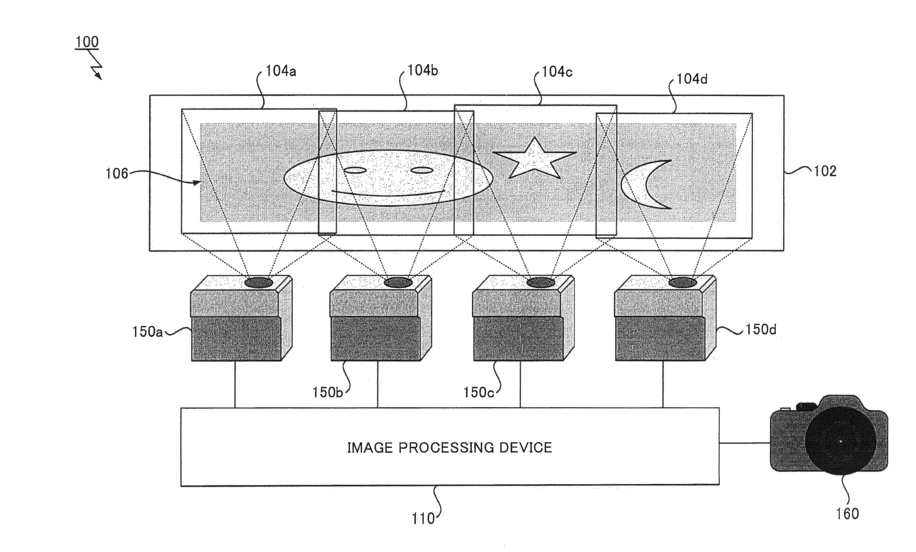
[0043]FIG. 1 is a schematic diagram that illustrates a general configuration of a projection system 100 according to the present embodiment. The projection system 100 illustrated in FIG. 1 is configured to include an image processing device 110 for executing overall control of such a system, a plurality of projectors 150, and a camera 160. Here, in a described embodiment, the projection system 100 is configured to be adapted to a so-called large-screen multi-projection wherein projection images from four projectors 150a-150d are synthesized on a...


PUM


Abstract

A projection system for projecting an image onto a projection body by a plurality of projection devices, includes an image preparation unit configured to prepare a plurality of imaging images for calibration, a grid point extraction unit configured to extract a set of grid points that indicates a distortion of a projection image for at least one projection device from each of the plurality of imaging images for calibration, a grid point transformation unit configured to execute a transformation between a plurality of images that are imaged in different imaging ranges on the plurality of imaging images for calibration in such a manner that each set of the grid points that are commonly extracted for a subject projection device is provided in a common coordinate system, a grid point synthesis unit configured to produce a set of the grid points that are synthesized for a subject projection device based on a plurality of sets of the grid points in the common coordinate system, and a correction coefficient calculation unit configured to calculate a correction coefficient for a subject projection device based on a set of the synthesized grid points.

Description

BACKGROUND OF THE INVENTION[0001]1. Field of the Invention[0002]An aspect of the present invention relates to at least one of a projection system, an image processing device, and a projection method.[0003]2. Description of the Related Art[0004]Conventionally, attention has been attracted by a multi-projection technique for arranging projection images from a plurality of projectors so as to have mutually overlapping areas and thereby projecting one image onto a screen at a high resolution.[0005]For example, the above-mentioned multi-projection technique is known by Japanese Patent No. 3,908,255. An image projection system in Japanese Patent No. 3,908,255 projects, from each projector onto a screen, a reference image that has four or more characteristic points with preliminarily known position coordinates. Herein, a reference image is a known image such as a grid pattern wherein, for example, bright spots or crosses are arranged at a constant interval. Then, positions of the above-men...

Claims


Application Information

Patent Timeline
IPC IPC(8): H04N5/74H04N17/00
CPCH04N17/004H04N5/74H04N9/3147G06T3/08G03B21/147H04N9/3185
Inventor ISHIKAWA, MASAAKIUCHIYAMA, YUKINAKA
Owner RICOH KK