
Method and systems for decentralized interference management in a multi-antenna wireless communication system

a wireless communication system and interference management technology, applied in the field of wireless communications, can solve the problems of affecting the overall potential gain, the complexity of the solution scales with the number, and the optimal transmit/receive strategy of linear spatial filters that maximize the weighted sum of data rates of the system is not known

Inactive Publication Date: 2015-03-19
UNIV POLITECNICA DE CATALUNYA
View PDF5 Cites 24 Cited by
  • Summary
  • Abstract
  • Description
  • Claims
  • Application Information

AI Technical Summary

Benefits of technology

The patent describes a method for adjusting the transmit filters of base stations to minimize interference with other base stations and maximize the overall data rates of the system. This is done by optimizing the transmission criteria based on the interference cost matrix. The method also avoids the need for complex interfering channel estimation and reduces the impact of non-ideal backhaul links.

Problems solved by technology

Unfortunately, the optimal transmit / receive strategy with linear spatial filters that maximize the weighted sum of data rates of the system is not known because of the non-convexity of the problem.
Already existing centralized interference management approaches allow finding locally optimal solutions, but they require of a central unit to collect the Channel State Information (CSI) of all receivers, and further the complexity of the solution scales with the number of transmitters times number of receivers.
Hence, channel estimation errors on the interfering links and the overhead associated to the reporting of channel gains have a detrimental effect on the overall potential gains.
The method exploits Time Division Duplex (TDD) access mode and hence channel reciprocity, but it is not applicable to a multi-antenna transmission system.U.S. Pat. No. 8,023,955, incorporated by reference herein, enables decentralized schedulers by exploiting the reciprocity of radio channels in TDD or Frequency Division Duplex (FDD) systems by preemptively controlling inter-cell interference levels in the downlink transmission.

Method used


Image

  • Method and systems for decentralized interference management in a multi-antenna wireless communication system
  • Method and systems for decentralized interference management in a multi-antenna wireless communication system
  • Method and systems for decentralized interference management in a multi-antenna wireless communication system

Examples


embodiment 1

[0105]The knowledge of the interference cost matrix γi, (0), at BSi allows managing the interference created by BSi towards unintended UEs attached to other BSs.

[0106]In this regard, FIG. 2 illustrates how the DL transmit and receive filters are designed in a deployment with 2 BSs and 1 UE attached to each BS. First, each BSi designs its DL transmit filter Ti (along with Ri) based on the equation (0), using the knowledge of the channel matrix towards its associated UE Hi,i (201, 208), the weighting matrix Wi (203, 210) and an estimation of the interference cost matrix {circumflex over (γ)}i (202, 209). The design is done by solving the decentralized optimization problem in (0) (or one of the extended versions in (0), (0), (0) or (0)) with γi={circumflex over (γ)}i (204, 211). Then, the DL receive filter Ri is computed at each UEi (205, 212) by means of equation Error! Reference source not found.(0) based on the knowledge of the equivalent complex channel matrix towards its associate...

embodiment 2

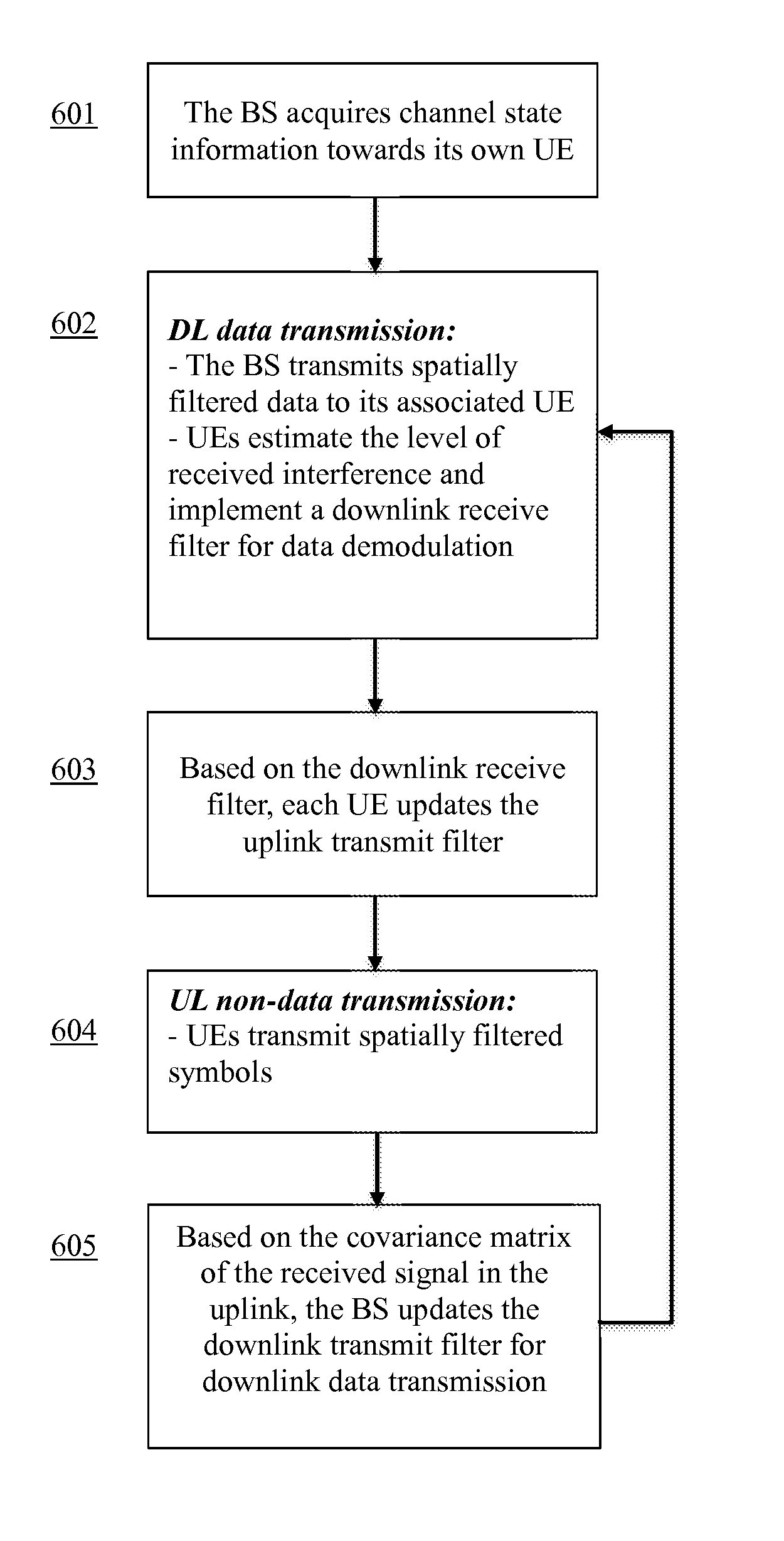
[0115]FIG. 6 illustrates the block diagram corresponding to Embodiment 2 as applied to a wireless cellular communication system. First, each base station BSi acquires or updates the knowledge of the complex channel matrix towards its own UEi Hi,i (601), which contains the channel gains between each UE antenna element and each BS antenna element. The channel state acquisition can be done either at the BS by exploiting channel reciprocity or at the UE and then reported to the BS. Once this information is available at BSi, the DL transmit and receive filters are calculated in a decentralized manner as it is described in Embodiment 1 and FIG. 2, and DL data transmission is carried out (602). Based on the knowledge of the DL receive filter at each UE, the UL transmit filter is designed as it is described in Embodiment 1 and FIG. 3 (603) and an UL non-data transmission is carried out (604). The UL non-data transmission by non-associated UEj allows BSi to estimate the interference cost mat...

embodiment 3

[0117]FIG. 7 illustrates the block diagram corresponding to Embodiment 3 as applied to the DL of a wireless cellular communication system. First, each base station BSi acquires or updates the knowledge of the complex channel matrix towards its own UEi Hi,i (701), which contains the channel gains between each UE antenna element and each BS antenna element. The channel state acquisition can be done either at the BS by exploiting channel reciprocity or at the UE and then reported to the BS. Once this information is available at BSi, the DL transmit filters are calculated in a decentralized manner as it is described in Embodiment 1 and FIG. 2, and DL non-data transmission is carried out (702). Based on the knowledge of the received interference-plus-noise at each UE, the UL transmit filter is designed as it is described in Embodiment 1 and FIG. 3 (703) and an UL non-data transmission is carried out (704). The UL non-data transmission allows BSi to estimate the interference cost matrix b...


PUM


Abstract

A method that includes interference control at transmitters and interference mitigation at receivers in a wireless communication system is disclosed. Embodiments of the present invention exploit the interference sensitivity at neighboring terminals by taking into account the reciprocity of propagation radio channels in Time Division Duplexing systems (TDD). It can be applied to design the resource allocation for downlink (DL) and uplink (UL) transmissions in a wireless communication system. The methods include the self-configuration of the transmit power, the transmit precoder and the receive filter, at each transmitter and receiver in a multi-cell network. Systems are also provided and configured for implementing the methods of the invention.

Description

CROSS REFERENCE TO RELATED APPLICATIONS[0001]This application claims priority to U.S. Provisional Patent Application No. 61 / 862,566, filed Aug. 6, 2013, the contents of such application being incorporated by reference herein.FIELD OF THE INVENTION[0002]This invention relates to the field of wireless communications. More specifically, the invention relates to methods and systems for decentralized managing of interference in multi-antenna systems, that includes transmitter design for controlling the generated interference and receiver design for mitigating the interference, through the self-configuration of the transmit power, the transmit precoding, and the receive filter, in a multi-cell network based on Time Division Duplexing (TDD). The proposed methods rely on propagation channel reciprocity for decentralized interference management. The invention is applicable to, but not limited to, a communication resource access, particularly for an enhanced downlink or uplink packet-based da...

Claims


Application Information

Patent Timeline
IPC IPC(8): H04W24/02H04B7/04H04L5/14
CPCH04W24/02H04B7/04H04L5/1438H04B7/024H04B7/0404H04B7/0413H04B7/0426H04B7/0456H04B7/0617H04B7/0619H04L5/0033H04L5/0073H04L5/1469H04W52/04H04W52/143H04W52/243
Inventor LAGEN MORANCHO, SANDRAAGUSTIN DE DIOS, ADRIANVIDAL MANZANO, JOSEP
Owner UNIV POLITECNICA DE CATALUNYA
Learn More