Portable radiographic imaging apparatus and system

a radiographic imaging and portable technology, applied in electrical devices, medical science, diagnostics, etc., can solve problems such as affecting image transmission time, communication failure, and inability to maintain constant high quality in communication, and achieve the effect of reducing the influence of communication failure on image transmission time and other issues

Active Publication Date: 2015-03-19
FUJIFILM CORP
View PDF1 Cites 29 Cited by
  • Summary
  • Abstract
  • Description
  • Claims
  • Application Information

AI Technical Summary

Benefits of technology

[0019]In view of the foregoing problems, an object of the present invention is to provide a portable radiograph

Problems solved by technology

However, the radio communication is influenced by radio interference of various forms, for example, with radio waves emitted by a portable terminal device of radio communication manually carried by a nurse, physician and the like, and electromagnetic noise created by an electromagnetic medical instrument, such as a thermal treatment device and an electrocautery device.
A communication failure such as a delay may be created by influence of the radio interference in a communication environment where the portable terminal device or the electromagnetic medical instrument is present near to the X-ray imaging apparatus of the radio communication.
A problem arises in that a constantly high quality cannot be maintained in the communication.
The data size of the X-ray image is large in general, so that influence of the communication failure to the time of the image transmission is considerable.
However, there is a problem in the method in JP-A 2011-098025 in that causes of the communication failure corresponding to the communication environment of a newest state cannot be recognized correctly, as a method of producing the communication history by correlating the transmission speed with a time point and a stationary type of the imaging apparatus after measurement of the transmission speed in each event of the imagin

Method used


Image

  • Portable radiographic imaging apparatus and system
  • Portable radiographic imaging apparatus and system
  • Portable radiographic imaging apparatus and system

Examples


first preferred embodiment

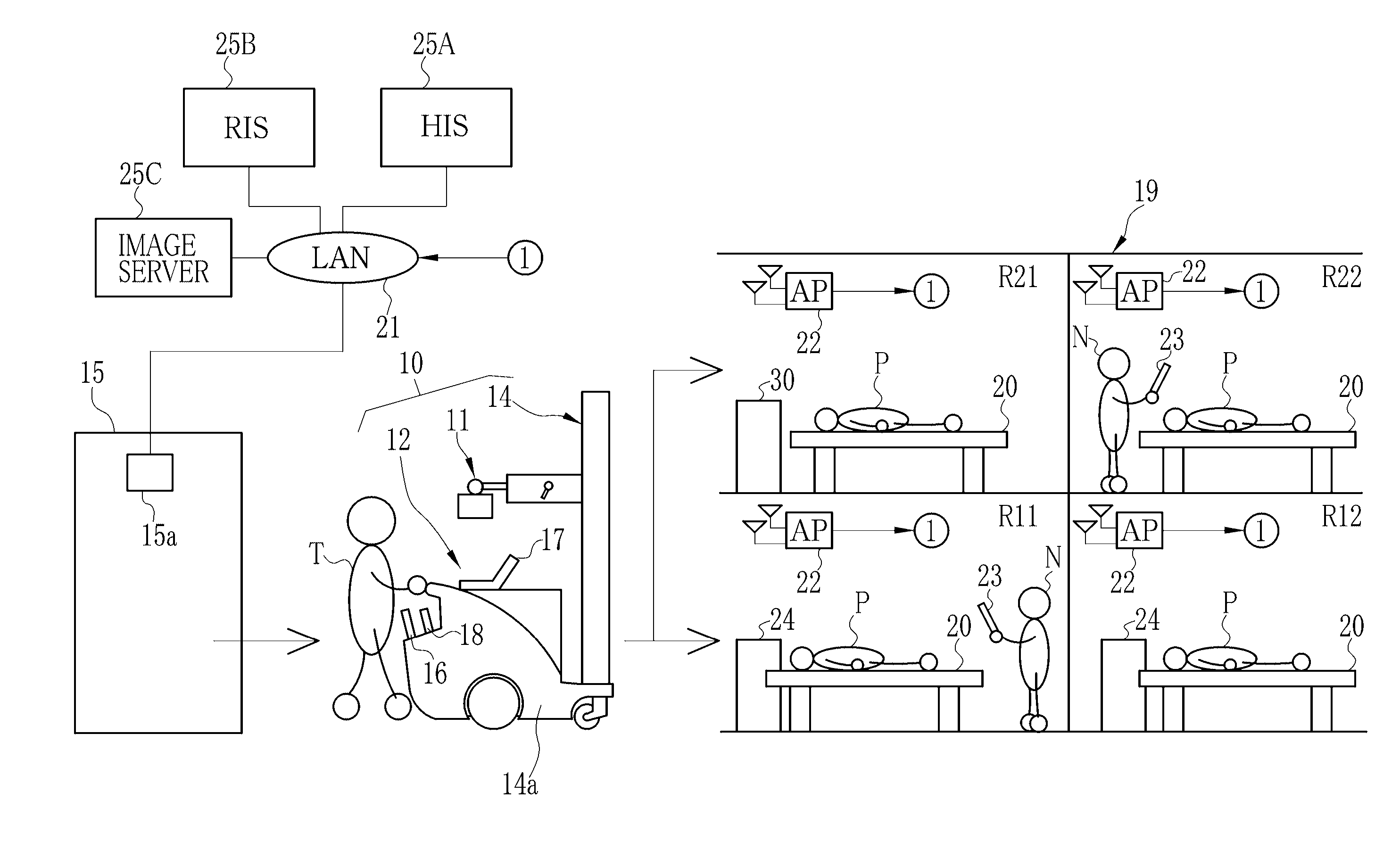
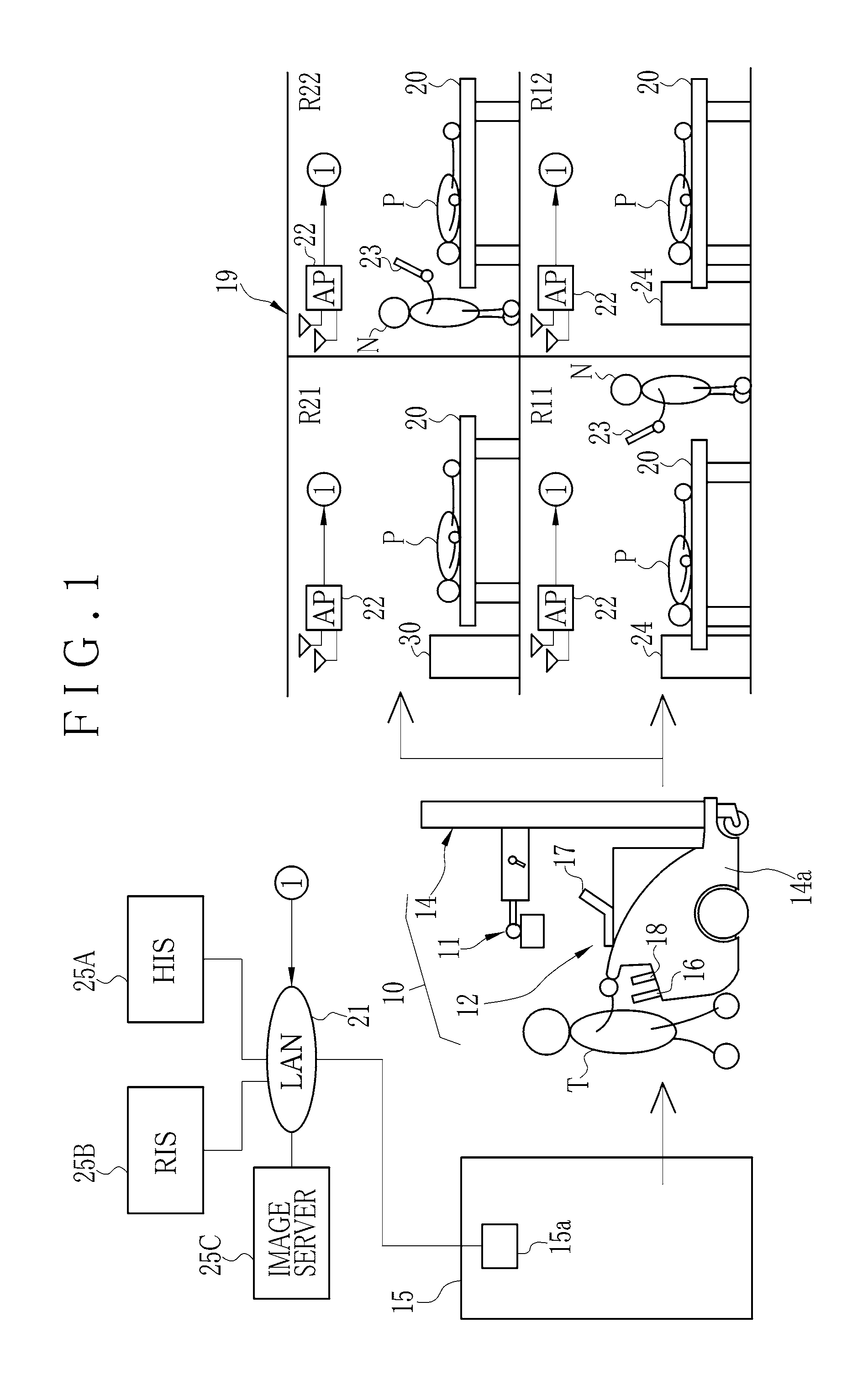
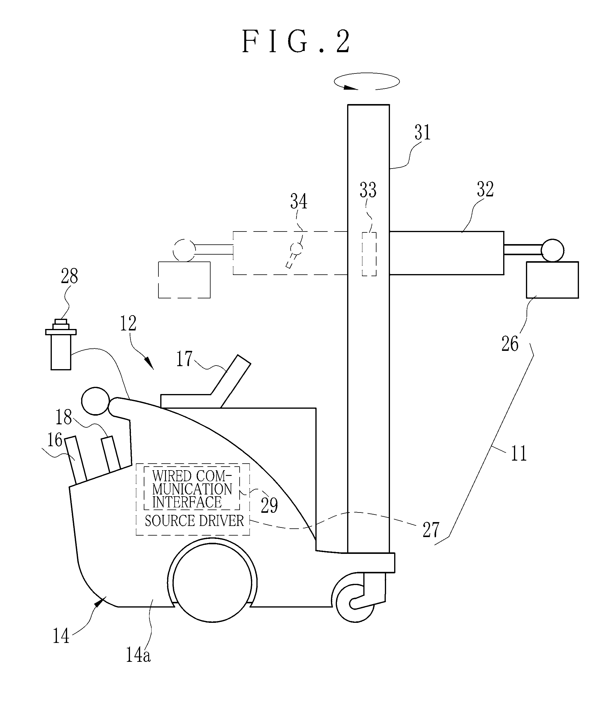
[0091]In FIG. 1, a portable X-ray imaging system 10 or portable radiographic imaging system includes a portable X-ray source apparatus 11 or portable radiation source apparatus, and a portable X-ray imaging apparatus 12 or portable radiographic imaging apparatus. A medical cart 14 is constituted by the X-ray source apparatus 11 and a cart platform 14a. The cart platform 14a has rotatable wheels for movement, so that the X-ray source apparatus 11 is usable as a mobile apparatus. The X-ray imaging apparatus 12 includes an electronic cassette 16, a portable console unit 17 or user interface unit, and a control interface unit 18 or functional unit, and can be carried by the medical cart 14. There is a storage space 15 where the medical cart 14 is stored in the hospital facility while the medical cart 14 is not used. For imaging in medical service, the X-ray imaging apparatus 12 is placed on the medical cart 14 which is moved out of the storage space 15. In a hospital facility 19, a tech...

second preferred embodiment

[0245]In the above embodiment, the passive monitoring is started upon an output of an unlock signal of the medical cart 14. FIG. 32 illustrates another preferred embodiment, in which the passive monitoring is started by transmitting a first trigger signal from the medical cart 14 in the step S1011, upon engaging the lock mechanism 33 of the medical cart 14 in the step S1010 in the storage space 15. In case the lock mechanism 33 is released upon entry in a hospital room in the step S1040, the passive monitoring is terminated in the step S1041. Therefore, the passive monitoring is continued until the entry in the hospital room from the storage space 15 in the step S1020. It is possible to collect information of communication environment around the hospital room in addition to the inside of the hospital room of the in-patient care. Assuming that the number of the particular medical instruments 30 is high in the hospital facility 19, it is possible to prevent failure in detecting the pa...

third preferred embodiment

[0251]It is likely in the first embodiment that a communication failure is caused by a blocking object or a relative position of the X-ray imaging apparatus 12 as described with the example pattern 6 of Table 1. For example, the medical cart 14 can be moved as illustrated in FIG. 33 to adjust the relative position between the console unit 17 and the control interface unit 18 on the medical cart 14 and the electronic cassette 16 on the hospital bed 20, so that a transmission speed may be raised effectively. Ina third preferred embodiment, an assist function (aid function) for the position adjustment is added to the X-ray imaging apparatus 12 of the first embodiment. For the remaining elements in the structure, the first embodiment is repeated.

[0252]In FIG. 34, the console unit 17 of FIG. 7 is repeated but with a difference in additionally having a positioning aid device 110 or position estimation device, and a position sensor 111.

[0253]The position sensor 111 detects a position of th...


PUM


Abstract

A portable X-ray imaging apparatus includes an electronic cassette for imaging of an X-ray image and transmitting the X-ray image wirelessly. An image receiving unit communicates with the electronic cassette and receives the X-ray image wirelessly. A passive monitoring device receives ambient electromagnetic waves to measure communication environment by passive monitoring. An active monitoring device performs data communication between the electronic cassette and the image receiving unit to measure the communication environment by active monitoring. Furthermore, an evaluation device detects a cause of a communication failure by considering a result of the passive monitoring and a result of the active monitoring. The evaluation device detects that the cause of the communication failure is a blocking object blocking radio waves or a relative position between the electronic cassette and the image receiving unit according to the results of the passive and active monitoring.

Description

CROSS-REFERENCE TO RELATED APPLICATION[0001]This application claims priority under 35 USC 19 from Japanese Patent Application No. 2013-192468, filed 17 Sep. 2013, and Japanese Patent Application No. 2014-029991, filed 19 Feb. 2014, the disclosure of which is incorporated by reference herein.BACKGROUND OF THE INVENTION[0002]1. Field of the Invention[0003]The present invention relates to a portable radiographic imaging apparatus and system. More particularly, the present invention relates to a portable radiographic imaging apparatus and system in which causes of a communication failure can be estimated exactly and rapidly.[0004]2. Description Related to the Prior Art[0005]An X-ray imaging system or radiographic imaging system is widely used in medical service in a hospital. The X-ray imaging system includes an X-ray source apparatus or radiation source apparatus, and an X-ray imaging apparatus or radiographic imaging apparatus. The X-ray source apparatus generates X-rays. The X-ray im...

Claims


Application Information

Patent Timeline
IPC IPC(8): A61B6/00H04B1/38H04B7/26
CPCA61B6/563A61B6/4405H04B1/385H04B7/26A61B6/4283A61B6/4233
Inventor IWAMOTO, TAKAHIROTSUBOTA, KEIJINISHINO, NAOYUKIKUDO, YOSHIMITSU
Owner FUJIFILM CORP
Why Eureka
Try Eureka