Endoskopisches System

a technology of endoscopy and system, which is applied in the field of endoscopy system, can solve the problems of requiring a considerable amount of practice on the part of the operator and pain for the patient, and achieve the effects of improving operation, simple and safe insertion of the shaft, and improving operation

Active Publication Date: 2015-03-19
KARL STORZ GMBH & CO KG
View PDF3 Cites 5 Cited by
  • Summary
  • Abstract
  • Description
  • Claims
  • Application Information

AI Technical Summary

Benefits of technology

[0009]The object of the present invention is to make available an endoscopic system of the type mentioned at the outset, which permits easier operation, in particular simpler and safer insertion of the shaft through a curved access route into a cavity inside the body or into a curved hollow organ, and which also permits improved operation when performing an endoscopic procedure.

Problems solved by technology

A forward movement of this kind requires a considerable amount of practice on the part of the operator and, despite this, is often painful for the patient and associated with risks.

Method used


Image

  • Endoskopisches System
  • Endoskopisches System
  • Endoskopisches System

Examples


first embodiment

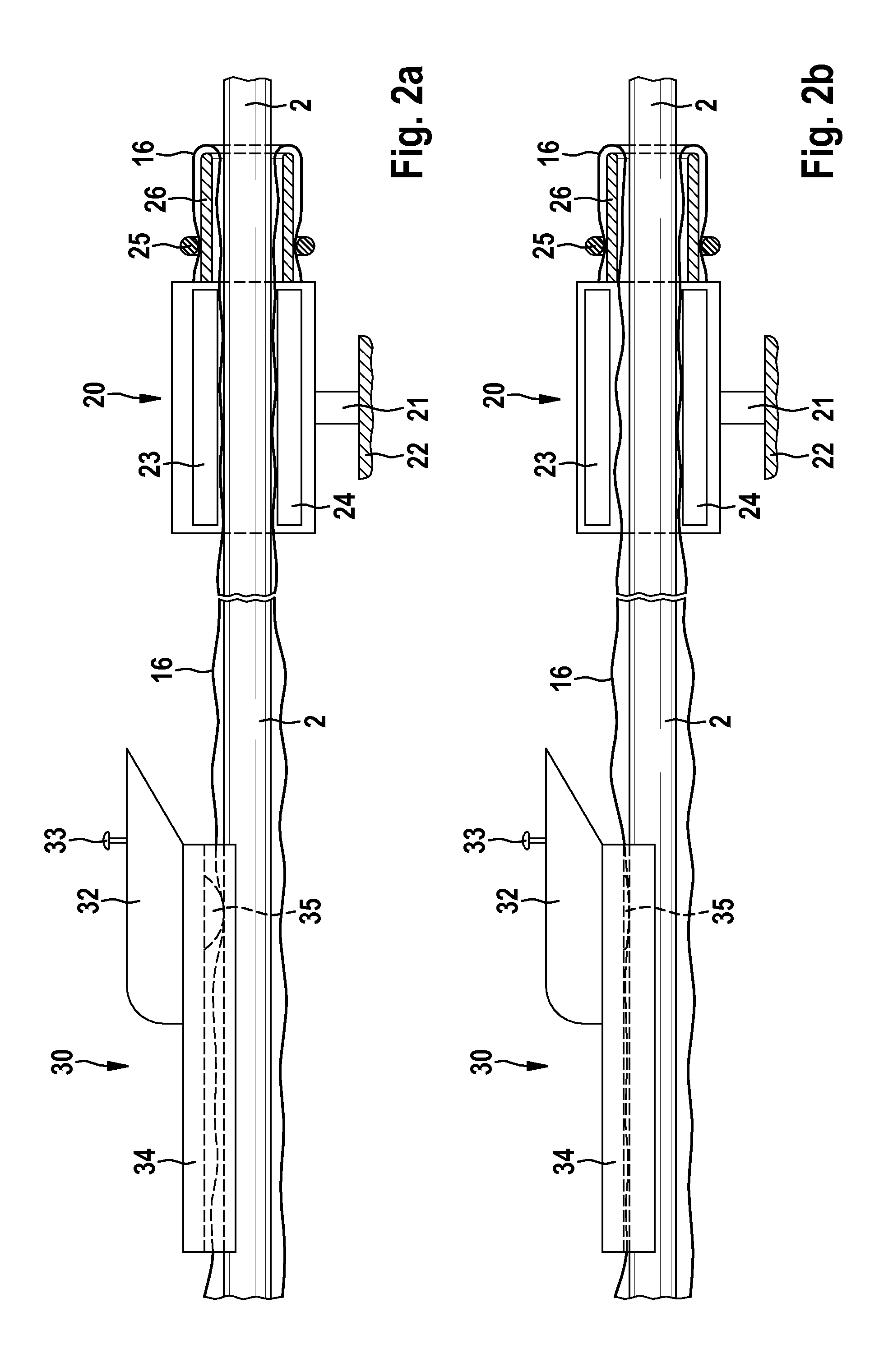
[0044]In the shaft stop 20, as is shown in FIG. 2a, a first portion of the shaft 2 is guided through the shaft stop 20, which is secured on the patient support 22 by the mount 21. The shaft stop 20 comprises a locking mechanism, which is formed by a movable pressure plate 23 and a stationary counter-pressure plate 24, wherein the movable pressure plate 23 can be moved toward and away from the counter-pressure plate 24 by motor. The pressure plate 23 and the counter-pressure plate 24 can be provided with a friction-enhancing surface and with a padding for increasing the friction with the shaft portion inserted between them and for avoiding damage to the shaft. To make it easier to insert the shaft 20 between the pressure plate 23 and the counter-pressure plate 24, the pressure plate 23 for example can be secured on a pivotable retainer (not shown). The shaft stop 20 furthermore has a flexible bow 25 forming a through-opening through which the shaft 2 is guided. Arranged at the distal...

second embodiment

[0049]In the shaft stop shown in two views in FIGS. 3a and 3b, the shaft stop comprises a locking mechanism, which is secured on the patient support 22 with the mount 21, and a shaft guide which is separate from the locking mechanism and, for example, is movable relative to the latter on a rail. The locking mechanism is formed by a movable pressure plate 23 and a stationary counter-pressure plate 24, wherein the movable pressure plate 23 can be moved toward and away from the counter-pressure plate 24 by motor in order to respectively lock and release the shaft 2 in terms of a movement in the longitudinal direction. The pressure plate 23 is secured on a swivel arm 23′. The shaft guide comprises a retainer bushing 27 through which the shaft 2 is guided. The retainer bushing 27 is held by a rubber band 25′ in a fork 28, which is secured on the patient support 22. Notches 29 lying opposite each other in the outer face of the retainer bushing 27 allow the retainer bushing 27 to be held w...


PUM


Abstract

An endoscopic system according to the invention, in particular for colonoscopy, includes a flexible endoscope with an elongate, flexible shaft, a regulator part, and also an operating part which can be placed on or pushed onto the shaft and which has at least one control element, wherein the endoscopic system furthermore includes a shaft stop, which can be secured on a patient support and which has a locking mechanism, controllable by the at least one control element, for locking the shaft against movement in a longitudinal direction of the shaft.

Description

FIELD OF THE INVENTION[0001]The present invention relates to an endoscopic system, in particular an endoscopic system for colonoscopy.BACKGROUND OF THE INVENTION[0002]In an endoscopic examination of a cavity inside the body, for example a hollow organ, with the aid of a flexible endoscope, an elongate and flexible insertion shaft of the endoscope is inserted through a natural or artificially created opening of the body into the cavity to be examined inside the body. A lens system for generating an endoscopic image is arranged at the distal end of the insertion shaft. To record and convey the endoscopic image from the distal end area (i.e. remote from the observer) of the insertion shaft to a regulator part, which is arranged in a proximal end area (i.e. near the observer) of the shaft, it is possible, for example, for an ordered bundle of light guide fibers to extend inside the shaft. In this case, an endoscopic camera is usually arranged in or on the regulator part, but the regulat...

Claims


Application Information

Patent Timeline
Patent Type & Authority Applications(United States)
IPC IPC(8): A61B1/00A61B1/31A61B1/018
CPCA61B1/00147A61B1/31A61B1/018A61B1/00151A61B1/0016A61B1/0052A61B1/0004
Inventor AYRENSCHMALZ, ROBERTWIMMER, VIKTOR JOSEF
Owner KARL STORZ GMBH & CO KG
Why Eureka
Try Eureka