Eureka AIR delivers breakthrough ideas for toughest innovation challenges, trusted by R&D personnel around the world.

Control Device and Method for Operating a Control Device

Inactive Publication Date: 2015-03-26
ROBERT BOSCH GMBH
View PDF14 Cites 2 Cited by
  • Summary
  • Abstract
  • Description
  • Claims
  • Application Information

AI Technical Summary

Benefits of technology

The present invention provides a control device and a method for operating it using an acceleration sensor as a sensor unit. The acceleration sensor is a cost-effective and power-saving component that is subject to practically no wear. The sensor allows for precise measurement of rotary movement, making it suitable for controlling electrical and electronic devices. The acceleration sensor can detect and quantify rotation and / or translation movement of the actuating element, allowing for additional control functionalities without requiring additional sensor units. The technical effects of the invention include no sliding contacts subject to wear, economical and power-saving operation, and improved accuracy in control.

Problems solved by technology

It is disadvantageous that potentiometers have sliding contacts that wear away over time.

Method used


Image

  • Control Device and Method for Operating a Control Device
  • Control Device and Method for Operating a Control Device
  • Control Device and Method for Operating a Control Device

Examples


Embodiment Construction

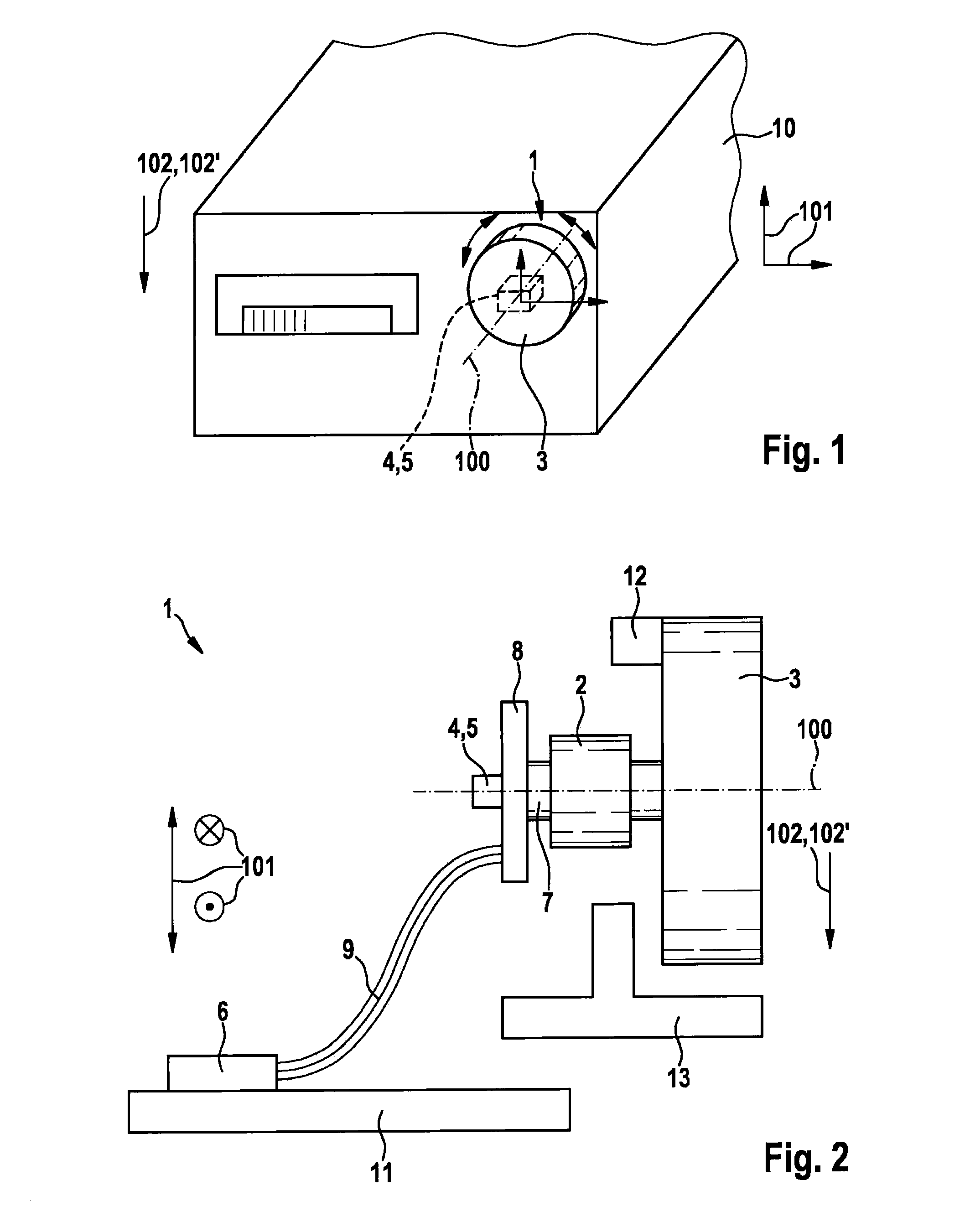
[0020]Identical components are consistently provided with the same reference numerals in the various drawings and are therefore normally named or mentioned only once.

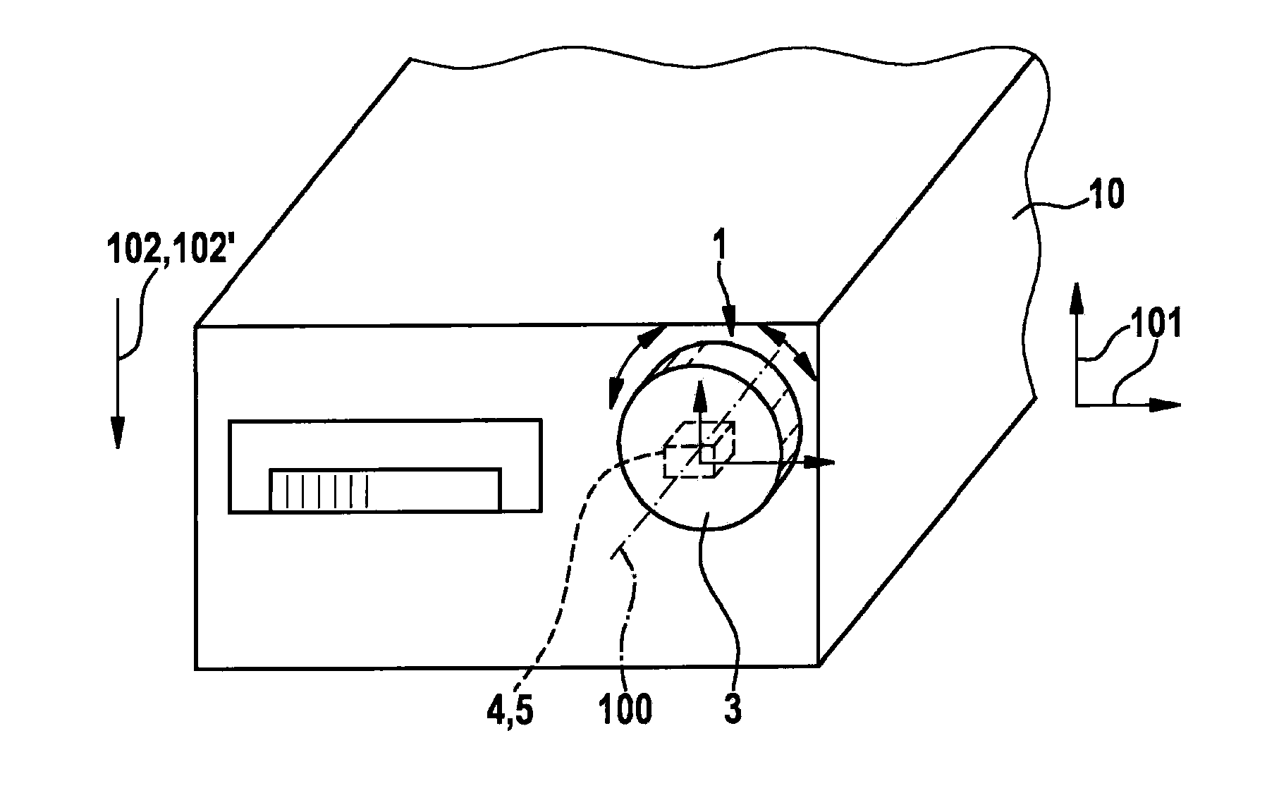
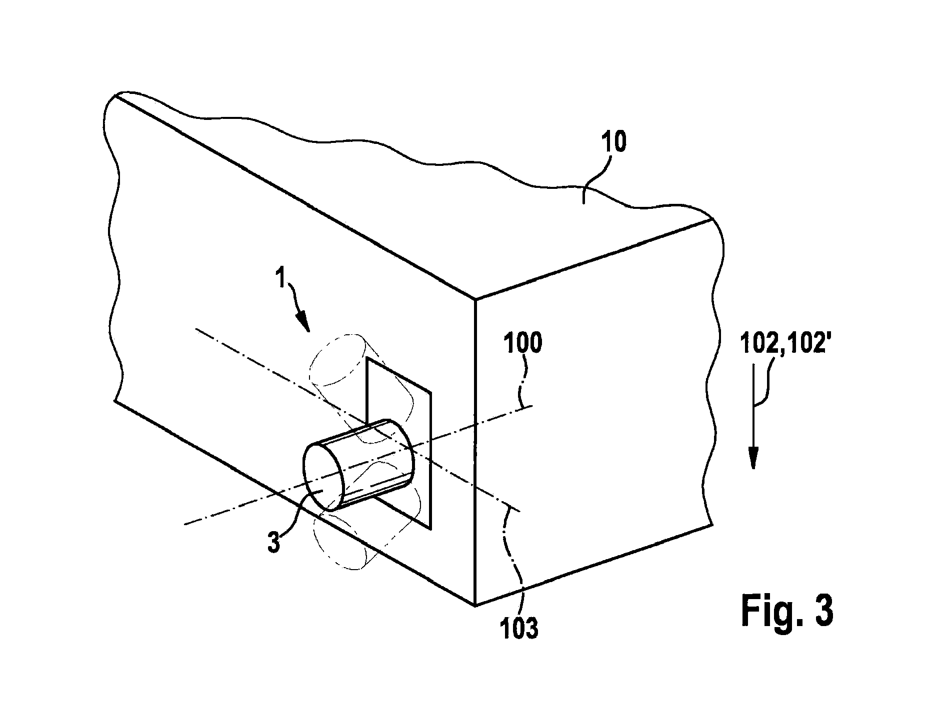
[0021]A schematic view of a control device 1 according to a first specific embodiment of the present invention is shown in FIG. 1. Control device 1 has an actuating element 3 to be operated manually by a user, the actuating element being rotatable about an actuation axis 100 in relation to a base element 2 configured as a friction bearing. Actuating element 3 is coupled non-rotatably via an axis 7 to a printed circuit board 8, a sensor unit 4 in the form of an at least biaxial micromechanical acceleration sensor 5 being situated on printed circuit board 8. Acceleration sensor 5 is coupled to an evaluation unit 6 via printed circuit board 8 and a flexible electrical conductor 9, for example, a flexible ribbon conductor, evaluation unit 6 being situated on a printed circuit board 11.

[0022]Control device 1 is used in parti...


PUM


Abstract

A control device, in particular for an electrical or electronic device, which has a base element and an actuating element which is manually rotatable in relation to the base element about an actuation axis, the control device further having a sensor unit for detecting a movement of the actuating element about the actuation axis, the sensor unit further including an acceleration sensor.

Description

FIELD OF THE INVENTION[0001]The present invention is directed to a control device.BACKGROUND INFORMATION[0002]Such control devices are believed to be generally understood. For example, a control knob, which has an actuating element which is rotatable in relation to a housing, is discussed in EP 0 842 822 A2. Such rotary knobs are used, for example, in car radios and the like. Normally, the actuating element is mechanically coupled to a potentiometer, the rotary position of the rotary knob being converted by the potentiometer into a corresponding electrical signal in order, for example, to set the sound volume of the car radio with the aid of the rotary knob. It is disadvantageous that potentiometers have sliding contacts that wear away over time.SUMMARY OF THE INVENTION[0003]The control device according to the present invention and the method according to the present invention for operating a control device as recited in the other independent claims have the advantage over the relat...

Claims


Application Information

Patent Timeline
IPC IPC(8): G01B21/22G01P15/18G01V7/02H01H19/14H01H3/32
CPCG01B21/22H01H19/14G01P15/18G01V7/02H01H3/32G01D5/12G01P15/00G05G1/08G06F3/0362G01C3/08
Inventor LAMMEL, GERHARDWEGELIN, FREDERIKFOERSTER, MARTINA
Owner ROBERT BOSCH GMBH
Why Eureka
Eureka Blog
Learn More