3D scanner using merged partial images

a technology of partial images and 3d scanners, applied in the field of structuredlight 3d scanners, can solve the problems of difficult problem, single line of light can yield only one 3d contour, and identify individual parts

Inactive Publication Date: 2015-03-26
3SHAPE AS
View PDF3 Cites 17 Cited by
  • Summary
  • Abstract
  • Description
  • Claims
  • Application Information

AI Technical Summary

Problems solved by technology

A particular problem to be solved with structured light scanners is the identification of individual parts of the light pattern in the images recorded by the camera.
The more dense the light pattern, and the more lines it contains, the more difficult the problem.
However, a single line of light can yield only one 3D contour.
Only few and expensive sensors are available that offer both a high pixel count and a high frame rate.
The problem is exacerbated because a 2D sensor is required to image the line of light distorted in any way, yet still a linear feature in the image; and thus only a small portion of all pixels provide useful data.
In many applications, the limiting factor for the scanning speed is the speed of movement of the scan head.
Increasing this speed alone will decrease the total scanning time, but at the cost of more sparse coverage on the scanned object.

Method used


Image

  • 3D scanner using merged partial images
  • 3D scanner using merged partial images
  • 3D scanner using merged partial images

Examples


Embodiment Construction

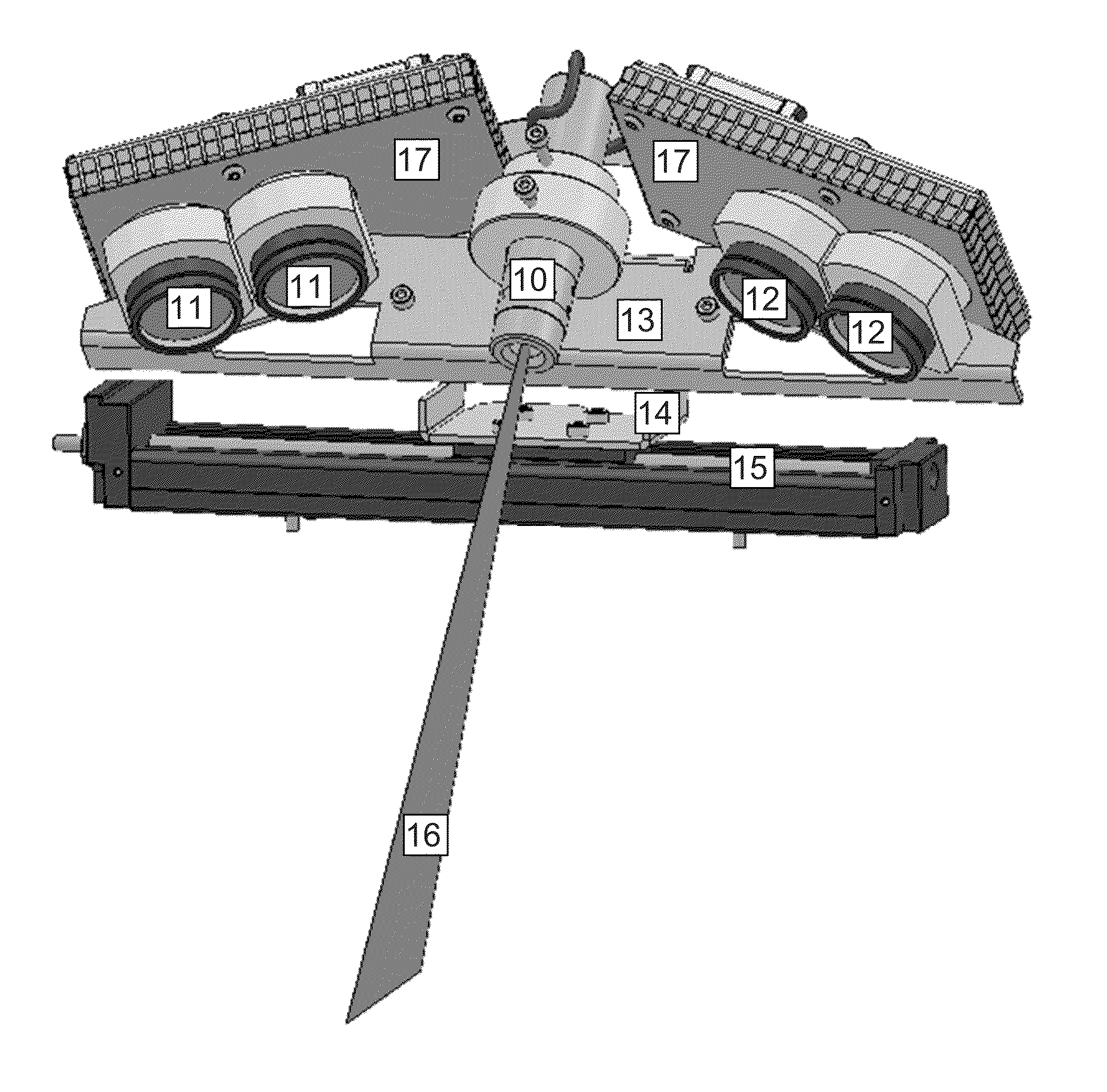
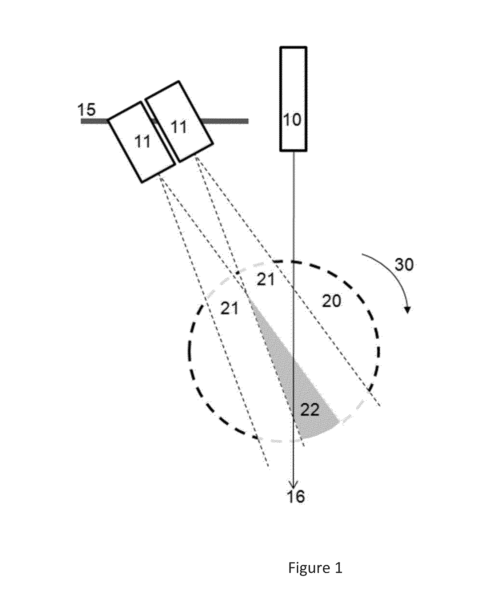
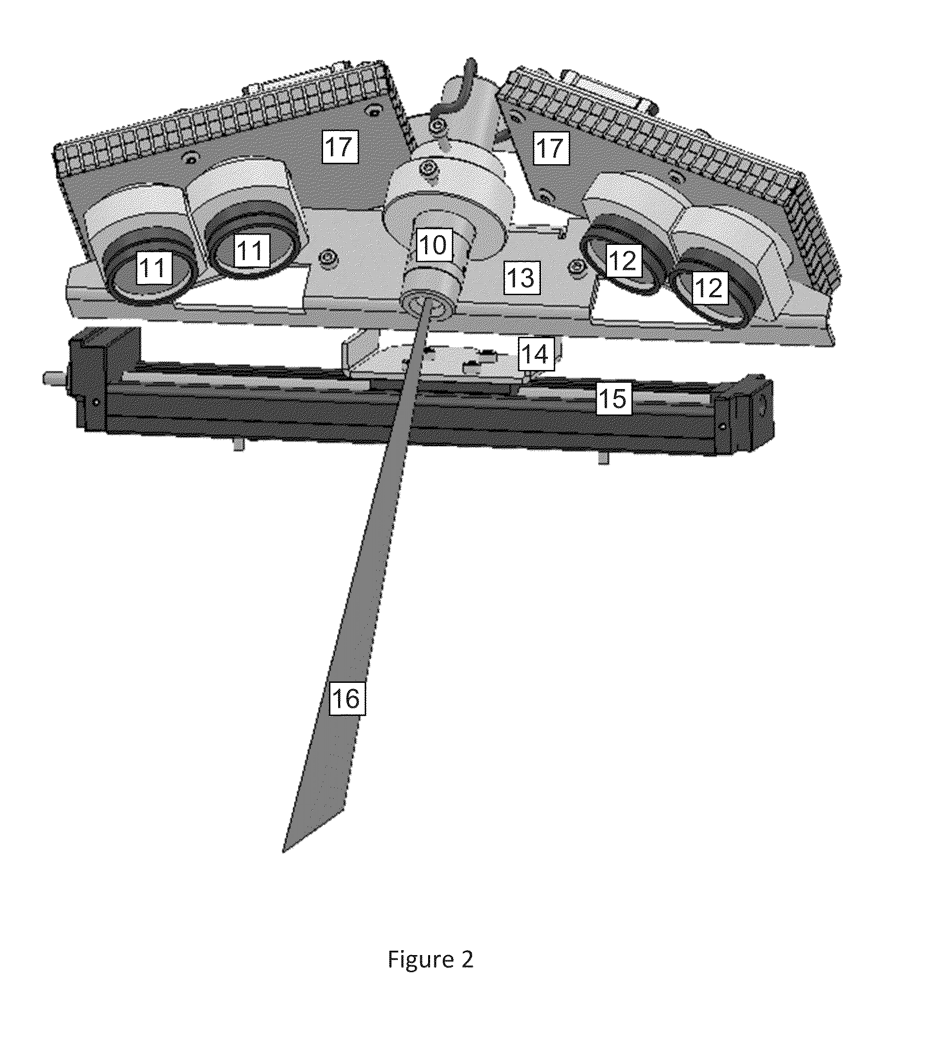
[0064]FIG. 1 shows a schematic of particular embodiment of the scanner according to the invention, as seen from above. A laser line generator 10 is the light source. It generates a fan of light—appearing as a single ray 16 from above—such that the light pattern is a line perpendicular to the plane of the figure. Two cameras 11 are mounted fixed to each other on one side of the light source. Together they can travel on a linear sweeping axis 15. The circular area 20 within the dashed line indicates the scan volume. The two cameras' fields of view are indicated by the intersection of area 20 and the two triangular areas 21, one for each camera 11. Finally, the overlapping field of view is indicated by the gray area 22. As indicated by the arrow 30, a target object contained in the scan volume can be rotated by a rotary axis (oriented perpendicularly to the plane of the figure and thus not shown). Note that in the sense of this invention, the field of view does not extend to infinity n...


PUM


Abstract

Disclosed is a structured light 3D scanner based on the principle of triangulation with a light source for generating a light pattern, two cameras with two-dimensional sensors recording the reflection of the light pattern from a target object, and one axis moving the cameras. Wherein the cameras are arranged with at least partly overlapping fields of view and where the sensors in the cameras are read out partially and concurrently during at least some period of the scanning process, thus providing partial images and where the partial images are merged prior to performing the triangulation calculations.

Description

FIELD OF THE INVENTION[0001]This invention relates to structured-light 3D scanners based on the principle of triangulation.BACKGROUND OF THE INVENTION[0002]A method for producing a digital three-dimensional model of a physical target object is to project a known light pattern onto the surface of the object, record the projected pattern with a camera containing a two-dimensional image sensor from a different angle and then compute the shape of the surface from the recorded deformation of the pattern. When the relative positions and the internal parameters of the projector and the camera are known then the three-dimensional shape of the illuminated part of the object can be computed using triangulation. This is known as structured light scanning and described in the prior art.[0003]A particular problem to be solved with structured light scanners is the identification of individual parts of the light pattern in the images recorded by the camera. The more dense the light pattern, and th...

Claims


Application Information

Patent Timeline
Patent Type & Authority Applications(United States)
IPC IPC(8): G01B11/25H04N13/02H04N13/239
CPCH04N13/0239G01B11/25G01B11/2545G01B2210/52H04N13/239
Inventor HOLLENBECK, KARL-JOSEFJENSEN, STEFAN ELMSTEDHOJGAARD, THOMAS ALLINOJELUND, HENRIK
Owner 3SHAPE AS
Why Eureka
Try Eureka