Lighting arrangement

a technology of lighting arrangement and led chip, applied in the direction of fixed installation, lighting and heating equipment, instruments, etc., can solve the problems of reducing overall brightness, affecting the effect of lighting arrangement, and affecting the perception of led chip light, etc., and achieves effective and reliable lighting arrangement. good

Active Publication Date: 2015-03-26
KONINKLIJKE PHILIPS ELECTRONICS NV
View PDF11 Cites 9 Cited by
  • Summary
  • Abstract
  • Description
  • Claims
  • Application Information

AI Technical Summary

Benefits of technology

[0028]Such a realisation of the light redirecting element can be suitable for lighting applications in which the light is usually only seen from directly in front of the light source, i.e. by an observer looking essentially directly at the emission face of the lighting arrangement. For example, the lighting arrangement according to the invention, with such a Fresnel realisation of the light redirecting element, can be put to good effect in an automotive lighting unit such as a combined stop/tail light or a Centre High Mount Stop Lamp (CHMSL). Such an automotive lighting unit according to the invention comprises a lighting arrangement in which the longitudinal planar emission face comprises a rectangular output surface of a Fresnel light

Problems solved by technology

A disadvantage of an LED is that the light emitted from the small area of the LED chip is perceived as a small, bright point of light.
However, some of the light can be lost in this way, and the overall brightness is diminished.
To better achieve the impression of a single light source, such lighting arrangements require diffusers or dedicated lenses to collect, refract and re-combine the light in the desired distribution, whereby such optical elements are always associated with some degree of loss.
Fur

Method used


Image

  • Lighting arrangement
  • Lighting arrangement
  • Lighting arrangement

Examples


first embodiment

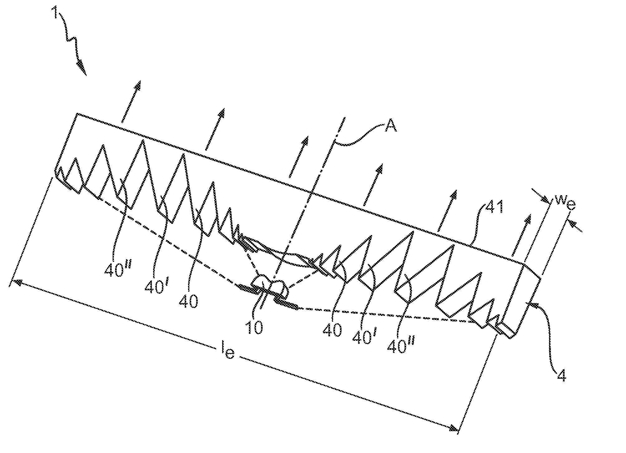
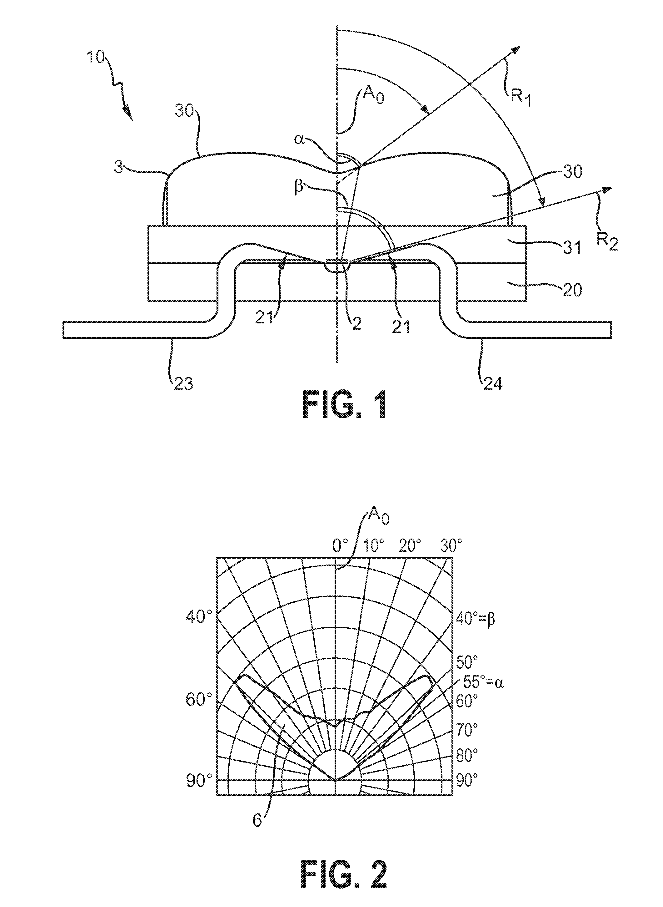
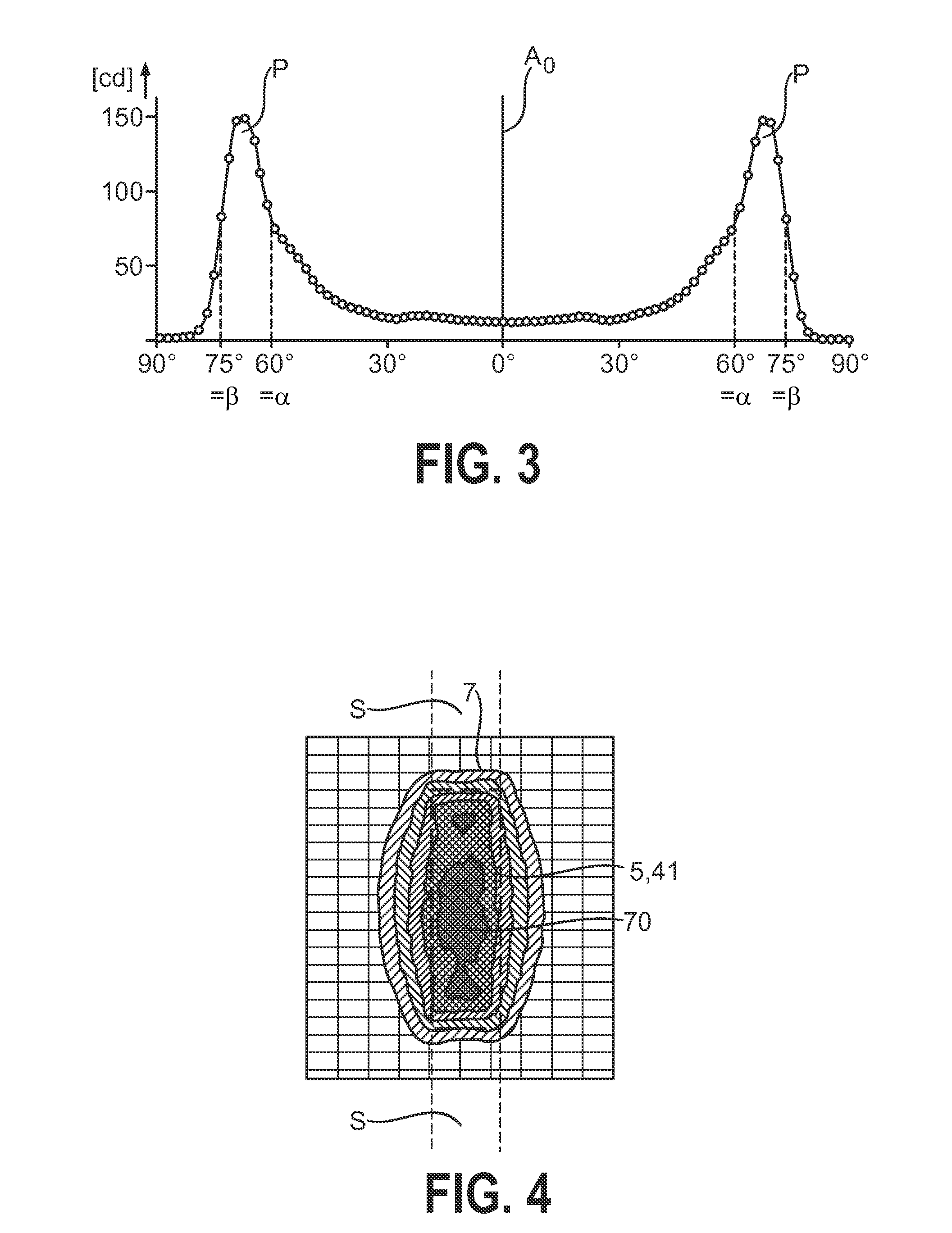
[0047]FIG. 6 shows a lighting arrangement 1 according to the invention. Here, the lighting element 10 is arranged below a Fresnel lens element 4, comprising a body with a plurality of lateral refracting prism elements 40, 40′, 40″, a central refracting portion, and an essentially rectangular emission face 41. The Fresnel lens element 4 is preferably formed in one piece, for example by an extrusion or milling process. The light emitted by the lighting element 10 is spread outward by the double-lobed spreading element such that a “batwing” characteristic is predominantly obtained, indicated here by the broken lines. The lateral refracting prism elements 40, 40′, 40″ are shaped to collect the light of various sectors of the “batwing” and refract the collected light essentially perpendicularly outward from the emission face 41 of the Fresnel lens 4. To an observer looking at the emission face 41, therefore, this appears as a uniform rectangular source of light with a length le and width...

second embodiment

[0049]FIG. 8 shows a lighting arrangement 1′ according to the invention. Here, the lighting element 10 is arranged below a translucent strip 5 that is coated with or otherwise treated to comprise a phosphor layer, indicated by the stippled pattern. The phosphor layer is illuminated by the batwing distribution of the light spread by the lighting element 10 when the enclosed LED is driven by a voltage across its electrodes. Since the phosphor collects the incident light and re-emits or scatters the light essentially uniformly according to the Lambert cosine law, i.e. the phosphor layer acts as an isotropic radiator, the effect of this lighting arrangement 1′ is to provide an evenly “emitting” surface 5 that itself appears to act as a light source 5. The light collected and emitted by the phosphor from a point on the translucent strip 5 is indicated here by groups of light rays emitted essentially uniformly in all directions. Such a lighting arrangement 1′ can be used to good effect to...


PUM


Abstract

Lighting arrangement (1, 1′) comprising a light source (2) for generating light; a spreading element (3) realised to laterally spread the generated light in a spreading plane (S), defined by an optical axis (AO) of the light source (2) and a longitudinal axis (L) of the spreading element (3), to give an essentially uniform quantity of light per unit area at an emission face (41, 51) orthogonal to the spreading plane (S) and parallel to the longitudinal axis (L) of the spreading element (3) and a light redirecting element (4, 5) arranged to collect the spread light, which comprises a longitudinal planar emission face (41, 51), and is realised to collect the laterally spread light and to emit the collected light essentially uniformly from the emission face (41, 51).

Description

FIELD OF THE INVENTION[0001]The invention describes a lighting arrangement, a lighting element, a light redirecting element, and a number of lighting units.BACKGROUND OF THE INVENTION[0002]With developments in light-emitting diode (LED) technology, lighting solutions that comprise LEDs instead of conventional light bulbs are becoming more popular. An LED comprises a semiconductor diode chip that emits light from an emitter surface. The emitter surface area is very small, usually in a region of only a few square millimetres, sometimes even only a few hundredths of a square millimetre. Such an LED chip can be a top-emitting device, or can emit from the top as well as from the sides. To protect the diode chip, it is usually sealed inside a protective cover, which can also act to improve light extraction. For example, a low-power LED chip inside a transparent plastic or epoxy cover for use as an indicator light of a domestic appliance is generally referred to as “packaged LED”. High-pow...

Claims


Application Information

Patent Timeline
IPC IPC(8): F21V5/04F21K99/00F21V13/04F21S8/10
CPCF21S48/215F21S48/2243F21S48/2262F21S48/2268F21S48/2281F21S48/2287F21V5/045G02B6/0016G02B6/003F21Y2101/02G02B6/0028F21K9/50F21S48/00F21V13/04F21Y2101/00F21S43/14F21S43/239F21S43/243F21S43/245F21S43/247F21S43/249F21K9/27F21K9/60F21Y2115/10F21S43/16F21V5/10H01L33/58F21V5/04
Inventor SPINGER, BENNOMARTIN, PAUL SCOTTBLOEMEN, PASCAL JEAN HENRITAI, KUOCHOU
Owner KONINKLIJKE PHILIPS ELECTRONICS NV
Why Eureka
Try Eureka