Matrix converter
- Summary
- Abstract
- Description
- Claims
- Application Information
AI Technical Summary
Benefits of technology
Problems solved by technology
Method used
Image


Examples
first embodiment
1. First Embodiment
(1.1. Configuration of Matrix Converter)
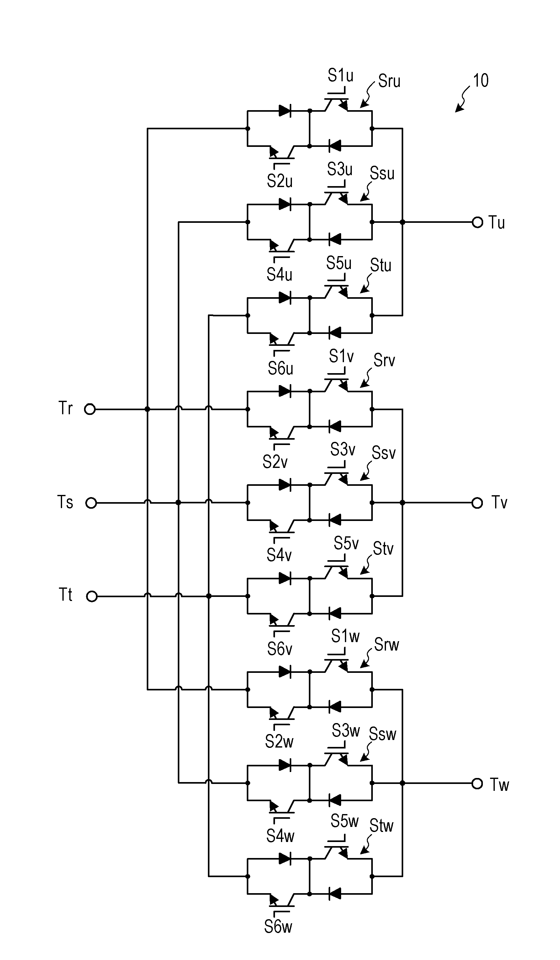
[0044]FIG. 1 is a diagram illustrating an exemplary configuration of the matrix converter according to a first embodiment. As illustrated in FIG. 1, a matrix converter 1 according to the first embodiment is disposed between a three-phase AC power supply 2 (hereinafter referred to simply as the AC power supply 2) and a load 3. The load 3 is, for example, an AC electric motor. In the following description, an R-phase, an S-phase, and a T-phase of the AC power supply 2 are described as input phases while a U-phase, a V-phase, and a W-phase of the load 3 are described as output phases.
[0045]The matrix converter 1 includes input terminals Tr, Ts, and Tt, output terminals Tu, Tv, and Tw, a power converter 10, an LC filter 11, an input voltage detector 12, an output electric current detector 13, and a controller 14. The matrix converter 1 converts a three-phase power to be supplied from the AC power supply 2 through the input termi...
second embodiment
2. Second Embodiment
[0141]The following describes a matrix converter according to a second embodiment. The matrix converter according to the second embodiment differs from the matrix converter 1 according to the first embodiment in that the matrix converter selects the commutation controller based on the input voltage phase. In the following description, the difference from the matrix converter 1 according to the first embodiment will be mainly described. Like reference numerals designate elements with corresponding or identical functions of the first embodiment, and therefore such elements will not be further elaborated here.
[0142]FIG. 21 is a diagram illustrating an exemplary configuration of a matrix converter 1A according to the second embodiment. As illustrated in FIG. 21, the matrix converter 1A according to the second embodiment includes the power converter 10, the LC filter 11, the input voltage detector 12, the output electric current detector 13, and a controller 14A.
[0143...
third embodiment
3. Third Embodiment
[0168]The following describes a matrix converter according to a third embodiment. The matrix converter according to the third embodiment differs from the matrix converters 1 and 1A according to the first and second embodiments in that the matrix converter selects the commutation controller based on the output electric current phase θo and the input voltage phase θi. Here, in the following description, the difference from the matrix converters 1 and 1A according to the first and second embodiments will be mainly described. Like reference numerals designate elements with corresponding or identical functions of the first embodiment, and therefore such elements will not be further elaborated here.
[0169]FIG. 24 is a diagram illustrating an exemplary configuration of a matrix converter 1B according to the third embodiment. As illustrated in FIG. 24, the matrix converter 1B according to the third embodiment includes a controller 14B. Here, the matrix converter 1B include...
PUM
 Abstract
Description
Claims
Application Information
 - R&D
- Intellectual Property
- Life Sciences
- Materials
- Tech Scout
- Unparalleled Data Quality
- Higher Quality Content
- 60% Fewer Hallucinations
Browse by: Latest US Patents, China's latest patents, Technical Efficacy Thesaurus, Application Domain, Technology Topic, Popular Technical Reports.
© 2025 PatSnap. All rights reserved.Legal|Privacy policy|Modern Slavery Act Transparency Statement|Sitemap|About US| Contact US: help@patsnap.com