Rivet bolt in combination with an attachment and process for making same

Active Publication Date: 2015-03-26
STAFAST PROD
View PDF2 Cites 5 Cited by
  • Summary
  • Abstract
  • Description
  • Claims
  • Application Information

AI Technical Summary

Benefits of technology

[0008]Yet another advantage of the present invention is space. Standard orbital riveters require considerable space. Using 4 standard orbital riveters to compress multiple rivet bolts simultaneously in one door sill is impossible. If the orbital riveters are customized so as to reduce the space they require, multiple orbital riveters may be used with substantially increased costs. Using multiple air cylinders/pistons as disclosed herein can easily handle a 9 inch centerline spacing from one rivet bolt to the next using standard air cylinders.
[0009]A process for making a rivet bolt in combination wit

Problems solved by technology

Standard orbital riveters require considerable space.
Using 4 standard orbital riveters to compress multiple rivet bolts simultaneously in one door sill is impo

Method used


Image

  • Rivet bolt in combination with an attachment and process for making same
  • Rivet bolt in combination with an attachment and process for making same
  • Rivet bolt in combination with an attachment and process for making same

Examples


Example

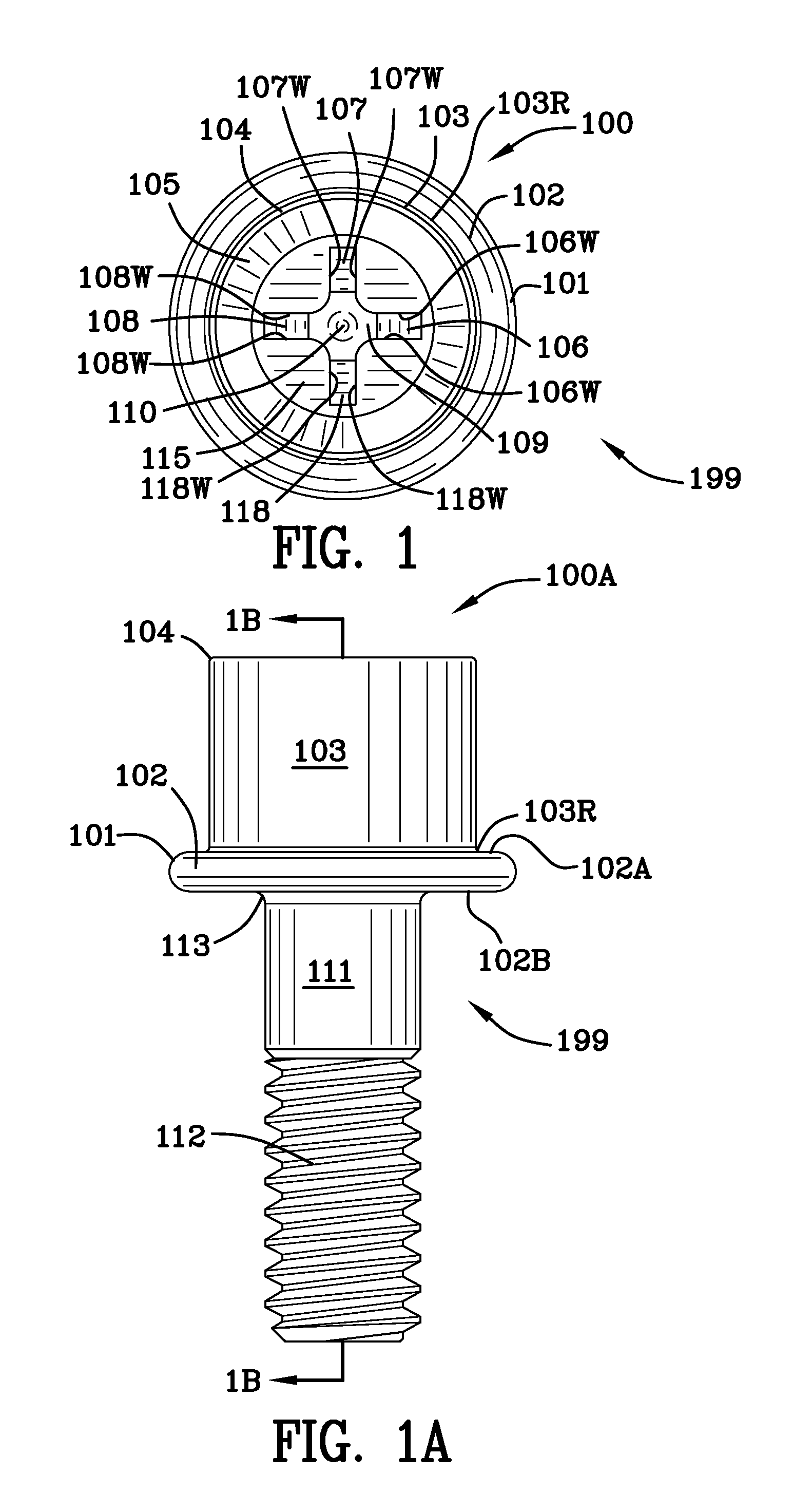
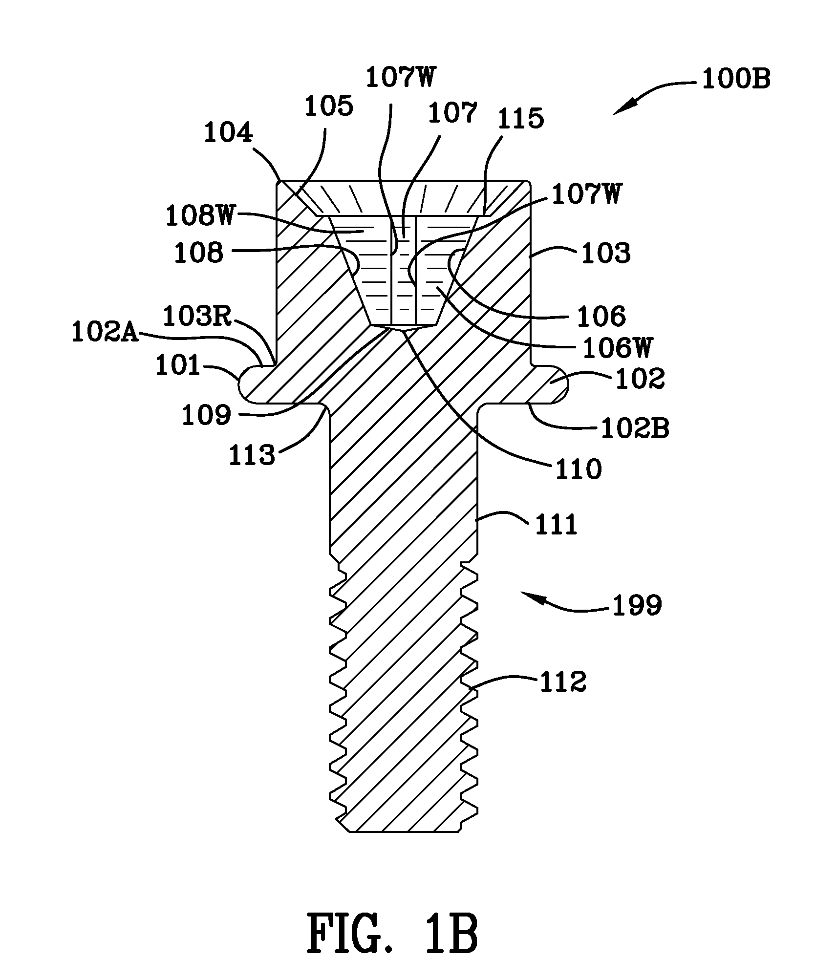
[0097]FIGS. 3, 3A, 3B, 3C and 3D represents a second embodiment or example of the rivet bolt 199A. The example of rivet bolt 199A has several structural features which are common with the example or embodiment set forth in FIGS. 1, 1A, 1B, 1C, 1D and, as such, the structures which are common will not be described again. FIG. 3 is a top view 300 of the rivet bolt 199A illustrating an upper cylindrical portion 103 having an interior thereof which is hexagonally shaped. FIG. 3 illustrates inverted frusto-conical surface 325 which extends from the upper edge 104 of the cylindrical upper portion 103 to hexagonal interior surfaces 301, 302, 303, 304, 305 and 306. Deformed inverted frusto-conical surface 325D is best viewed in FIGS. 3C and 3D.

[0098]Hexagonal interior surfaces 301, 302, 303, 304, 305 and 306 are illustrated in FIG. 3. FIG. 3A is a side view 300A of the rivet bolt 199A. FIG. 3B is cross-sectional view 300B of the rivet bolt 199A taken along the lines 3B-3B of FIG. 3A. A hexa...

Example

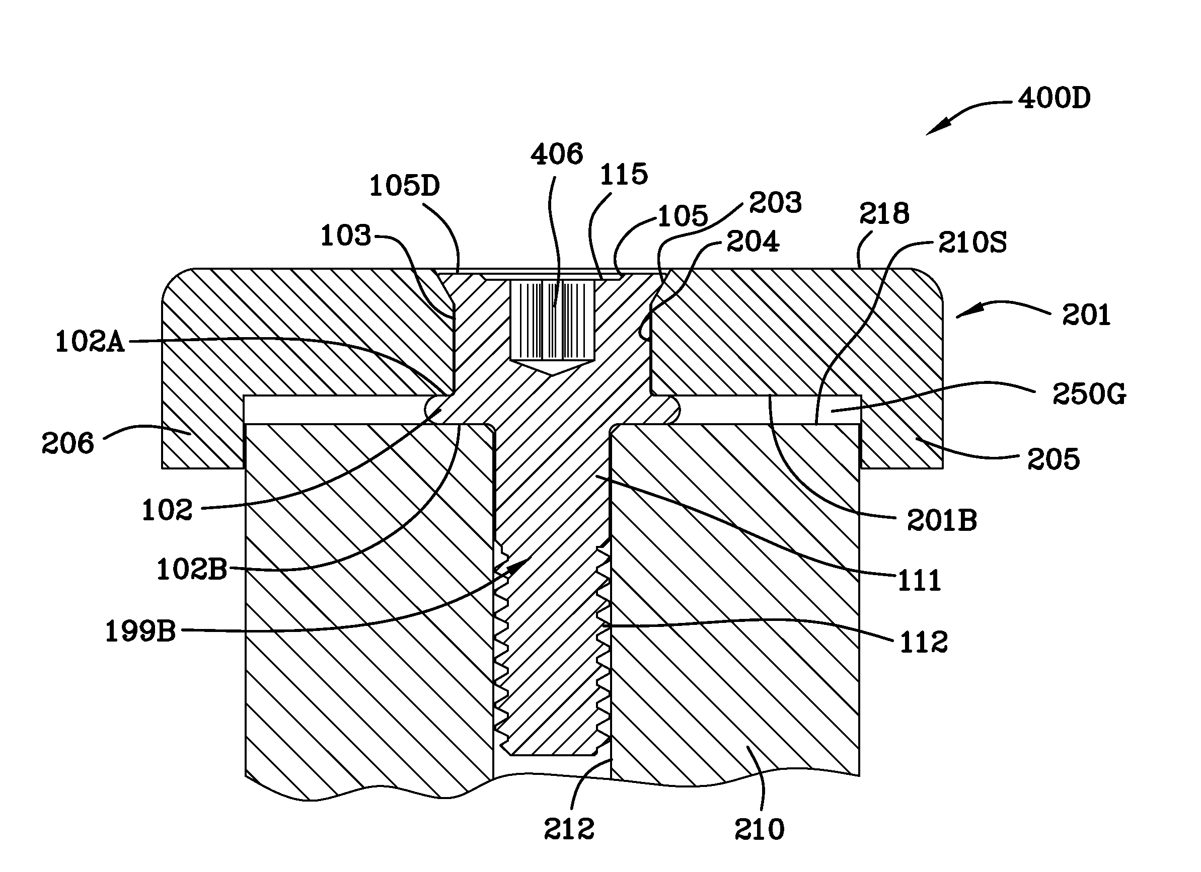
[0101]FIG. 4 is a top view 400 of a third embodiment or example of the rivet bolt 199B. The example of rivet bolt 199B has several structural features which are common with the example or embodiment set forth in FIGS. 1, 1A, 1B, 1C, 1D and, as such, the structures which are common will not be described again. FIG. 4 is a top view 400 of the rivet bolt 199B illustrating an upper cylindrical portion 103 having an interior thereof which is torx shaped. FIG. 4 illustrates inverted frusto-conical surface 105 which extends from the upper edge 104 of the cylindrical upper portion 103 to interior base surface 115. Deformed inverted frusto-conical surface 105D is best viewed in FIG. 4D.

[0102]FIG. 4B is cross-sectional view 400B of the rivet bolt 199B taken along the lines 4B-4B of FIG. 4A. FIG. 4A is a side view 400A of the rivet bolt 199B. A torx socket driver (not shown) detachably mates with the surfaces 401, 402, 403, 404, 405 and 406 and rotates the rivet bolt 199B. Although not shown, ...

Example

[0105]FIG. 5 is a top view 500 of a fourth embodiment or example of the rivet bolt 199C. The example of rivet bolt 199C has several structural features which are common with the example or embodiment set forth in FIGS. 1, 1A, 1B, 1C, 1D and, as such, the structures which are common will not be described again. FIG. 5 is a top view 500 of the rivet bolt 199C illustrating an upper cylindrical portion 103 having an interior thereof which is square shaped. Surfaces 501, 502, 503, and 504 are illustrated in FIG. 5.

[0106]FIG. 5 illustrates inverted frusto-conical surface 105 which extends from the upper edge 104 of the cylindrical upper portion 103 to interior base surface 115. Deformed inverted frusto-conical surface 105D is best viewed in FIG. 5D.

[0107]FIG. 5B is cross-sectional view 500B of the rivet bolt 199C taken along the lines 5B-5B of FIG. 5A. FIG. 5A is a side view 500A of the rivet bolt 199C. A square socket driver (not shown) detachably mates with the surfaces 501, 502, 503, a...


PUM

PropertyMeasurementUnit
Plasticityaaaaaaaaaa

Abstract

A rivet bolt in combination with an attachment wherein the rivet bolt includes: a flange having a top surface and a bottom surface, and, a shaft having a threaded portion. An upper cylindrical portion of the rivet bolt includes an upper edge and an interior base surface having a drive head socket. The attachment receives the rivet bolt and comprises: a top surface, a bottom surface, a cylindrical bore therethrough, and an inverted frusto-conical surface extending from the top surface to the cylindrical bore. The upper cylindrical portion of the rivet bolt is deformed and rotatably and slidingly engages the inverted frusto-conical surface extending from the top surface of the attachment to the cylindrical bore therethrough. The upper cylindrical portion of the rivet bolt resides partially within the cylindrical bore. A process for making a rivet bolt in combination with an attachment is disclosed.

Description

FIELD OF THE INVENTION[0001]This invention is in the field of rivet bolts used to join two substrates or devices together.BACKGROUND OF THE INVENTION[0002]Orbital riveters have been used in the past on relatively expensive rivet bolts. Orbital riveters are large and expensive. It is difficult to use multiple orbital riveters side by side as they occupy considerable space and, therefore, they cannot be easily used side by side to deform rivet bolt heads (upper portions) that are spaced relatively close together.[0003]U.S. Pat. No. 6,185,870, states, in the abstract, as follows: “[a} one-piece wood rivet having a first upper portion and a second lower portion is disclosed for use in adjustably securing a first piece of wood to a second piece of wood. A typical application of the rivet is the adjustment of a door threshold assembly. The first upper portion of the one-piece wood rivet includes a head and a flange. The second lower portion of the one-piece wood rivet includes a threaded ...

Claims


Application Information

Patent Timeline
IPC IPC(8): F16B23/00B23P19/04B21K1/46
CPCF16B23/0007F16B23/003B23P19/04F16B23/0038B21K1/463F16B23/0023B23P19/063B21J15/02F16B37/065Y10T29/49947
Inventor SELLE, STEPHEN R.
Owner STAFAST PROD
Why Eureka
Try Eureka