Structure for holding voltage detecting terminal

a technology for detecting terminals and structures, applied in current conducting connections, cell components, instruments, etc., can solve problems such as the increase in the amount of resin to be used, and the increase of part costs

Active Publication Date: 2015-03-26
YAZAKI CORP
View PDF2 Cites 7 Cited by
  • Summary
  • Abstract
  • Description
  • Claims
  • Application Information

AI Technical Summary

Benefits of technology

[0023]According to the configuration of the above (3), as the bent portion is formed by being bent substantially at a right angle, a shape hol

Problems solved by technology

Additionally, since the plate 109 becomes large by providing the supporting surface 113 in the plate 10

Method used


Image

  • Structure for holding voltage detecting terminal
  • Structure for holding voltage detecting terminal
  • Structure for holding voltage detecting terminal

Examples


Embodiment Construction

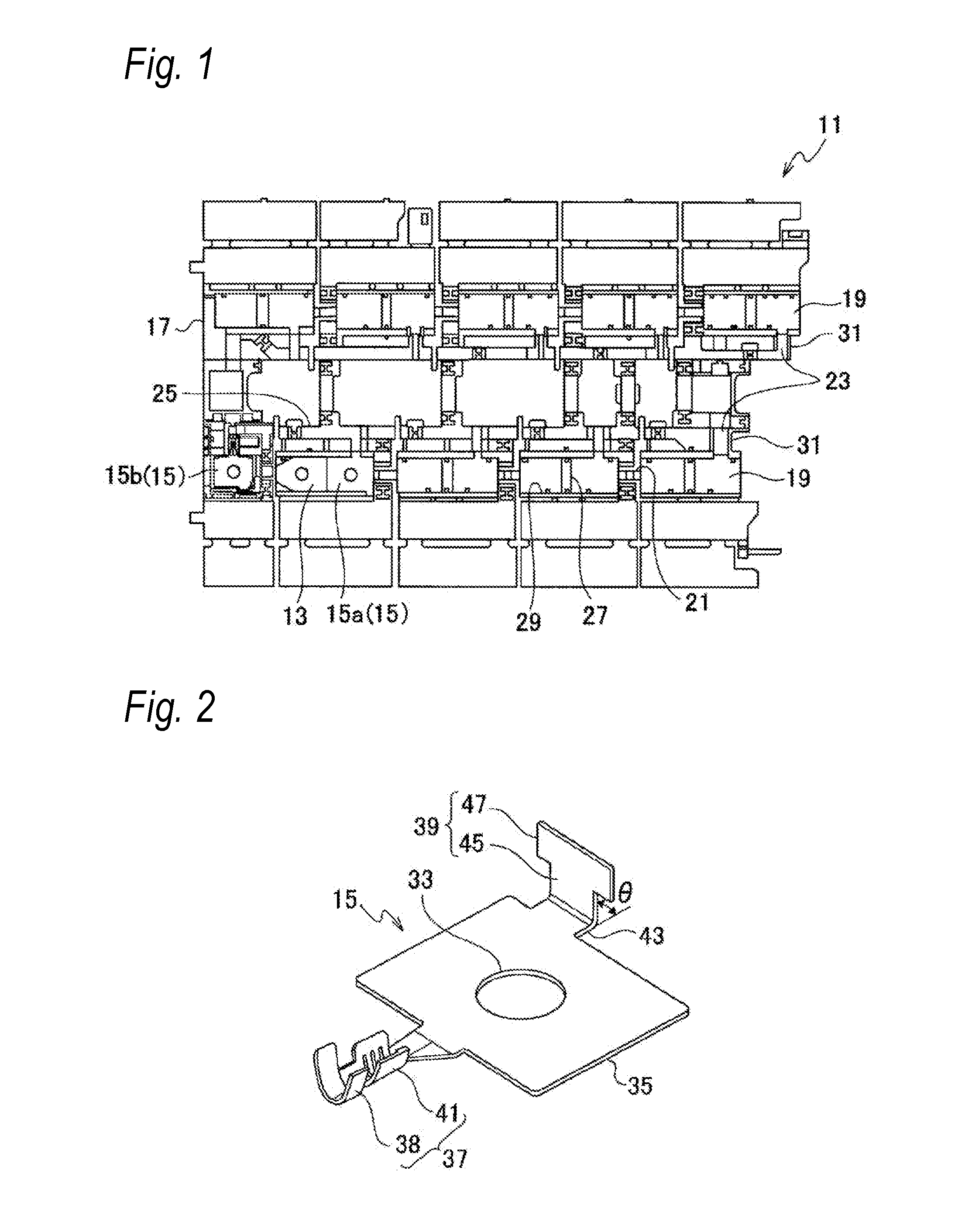
[0030]Hereinafter, an embodiment of a structure for holding a voltage detecting terminal related to the invention will be described with reference to the drawings. The structure for holding a voltage detecting terminal of the present embodiment is applied to, for example, a power supply device that is mounted on an electric car traveling with the driving force of a motor, a hybrid car traveling with the driving forces of both of an engine and a motor, or the like, and supplies electric power to the motor.

[0031]The power supply device of the present embodiment includes a battery assembly (not illustrated) and a busbar module to be described below. The battery assembly is configured, for example, by superimposing a plurality of batteries formed in the shape of a rectangular parallelepiped on each other. A pair of columnar electrode columns are provided so as to protrude from an electrode surface of each battery, one electrode column of these electrode columns is an electrode column (h...


PUM


Abstract

A voltage detecting terminal includes a flat plate-shaped electric contact portion having an insertion hole into which an electrode column of a battery is inserted, and a bent portion formed such that a tip is bent upward with respect to the electric contact portion. The bent portion is provided with a holding portion, and both ends of the holding portion in a plate width direction are expanded in the plate width direction, respectively. The voltage detecting terminal has a lower end surface of the holding portion in a thickness direction abutting against supporting surfaces of the plate and is held by a first housing portion.

Description

CROSS REFERENCE TO RELATED APPLICATIONS[0001]This application is a continuation of PCT application No. PCT / JP13 / 073,206, which was filed on Aug. 29, 2013 based on Japanese Patent Application (No. 2012-189898) filed on Aug. 30, 2012, the contents of which are incorporated herein by reference.BACKGROUND OF THE INVENTION[0002]1. Field of the Invention[0003]The present invention relates to a structure for holding a voltage detecting terminal.[0004]2. Description of the Related Art[0005]A power supply device that connects a plurality of batteries in series is mounted on motors, such as a hybrid car and an electric car. In this type of power supply device, a busbar module is mounted on a plurality of batteries (hereinafter referred to as a battery assembly) in which electrode columns of a positive electrode and a negative electrode are alternately arrayed and superimposed, and the respective batteries are connected in series. The busbar module includes a plurality of busbars each of which...

Claims


Application Information

Patent Timeline
IPC IPC(8): H01M2/10H01M2/20H01M50/209H01M50/50H01M50/503H01M50/507H01M50/51H01M50/569
CPCH01M2/20H01M2/10H01M10/48G01R31/364H01M50/51H01M50/503H01M50/569H01M50/507H01M50/209H01M50/50Y02E60/10
Inventor OGASAWARA, SHIGEYUKIYANAGIHARA, SHINICHIOTA, MICHIO
Owner YAZAKI CORP
Why Eureka
Try Eureka