
Dental treating apparatus and driving method for the same

a technology for treating apparatus and teeth, which is applied in the field of dental treatment apparatus, can solve the problems of reducing the efficiency of cutting and enlarging the root canal of teeth, reducing the efficiency of tooth cutting, and reducing the efficiency of root canal expansion, so as to prevent the breakage of a cutting tool and enhance the tooth cutting efficiency

Active Publication Date: 2015-03-26
MORITA MFG CO LTD
View PDF2 Cites 12 Cited by
  • Summary
  • Abstract
  • Description
  • Claims
  • Application Information

AI Technical Summary

Benefits of technology

The present invention is a dental treating apparatus that can prevent breakage of the cutting tool and enhance tooth cutting efficiency. It achieves this by controlling the rotation direction of the cutting tool based on the load applied to it. The cutting tool is rotated in the normal rotation direction for a predetermined angle and then the rotation direction is switched based on the load compared to a reference load. This ensures reliable driving in the normal rotation direction for cutting the tooth and improves the efficiency of work for cutting and enlarging the root canal of the tooth.

Problems solved by technology

However, the cutting tool for cutting and enlarging the root canal of the tooth cuts into the root canal wall and contributes to cutting of the tooth when rotated clockwise, for example, whereas the cutting tool does not cut into the root canal wall and does not contribute to cutting of the tooth when rotated counterclockwise.
Therefore, in the dental treating apparatus disclosed in Japanese National Patent Publication No. 2003-504113, the cutting tool is rotated clockwise or counterclockwise by the desired first rotation angle, and then, is rotated by the second rotation angle in the direction opposite to the first rotation angle, and thus, the rotation that does not contribute to cutting of the tooth is inevitably included, which resulted in a decrease in tooth cutting efficiency.
Therefore, in the dental treating apparatus disclosed in Japanese Patent No. 3264607, breakage of the cutting tool due to the applied load can be prevented, while the tooth cannot be cut while the load applied to the cutting tool is at the reference, which resulted in a decrease in efficiency of the work for cutting and enlarging the root canal of the tooth.

Method used


Image

  • Dental treating apparatus and driving method for the same
  • Dental treating apparatus and driving method for the same
  • Dental treating apparatus and driving method for the same

Examples


first embodiment

[0035]A dental treating apparatus according to a first embodiment of the present invention is a root canal treating device including a root canal enlarging and root canal length measuring system into which a dental hand piece for treatment on a root canal is incorporated. The dental treating apparatus according to the present invention is, however, not limited to the root canal treating device, and can be applied to a dental treating apparatus with a similar configuration.

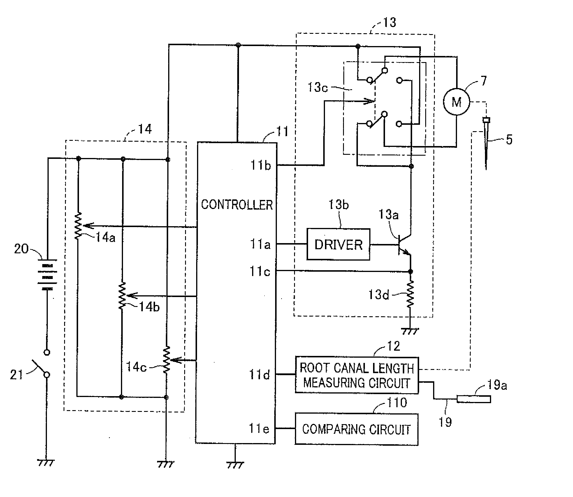
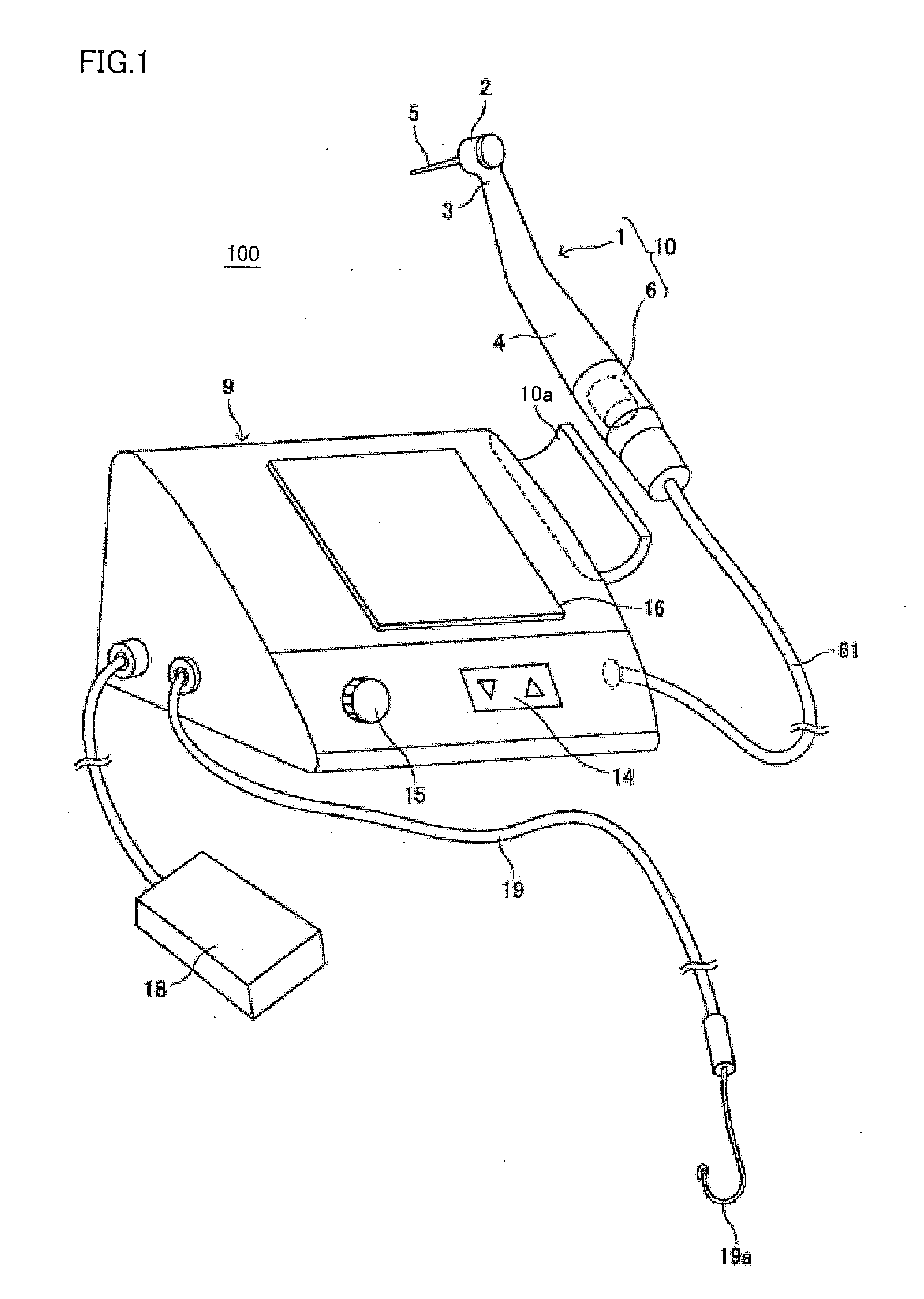
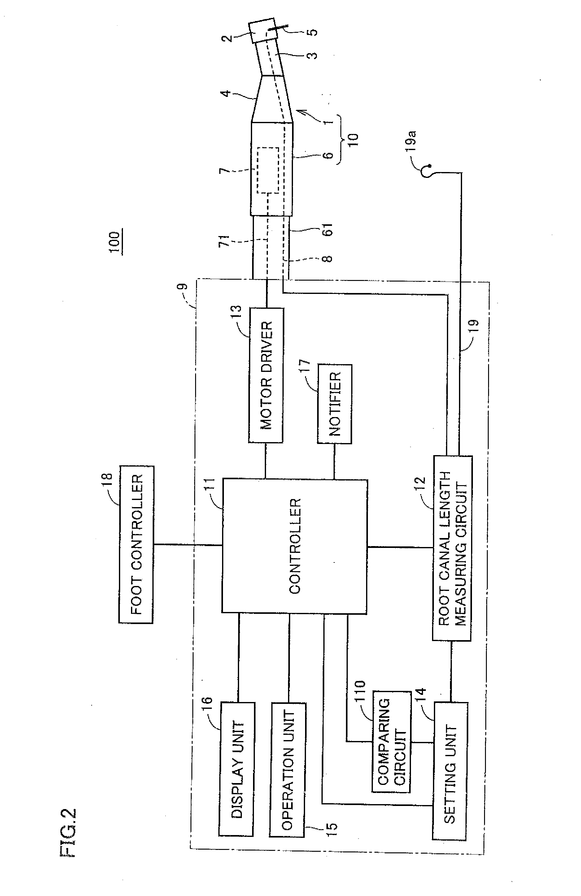
[0036]FIG. 1 is a schematic diagram showing an appearance of a configuration of the root canal treating device according to the first embodiment of the present invention. FIG. 2 is a block diagram showing a configuration of functions of the root canal treating device according to the first embodiment of the present invention. A root canal treating device 100 as shown in FIG. 1 includes a hand piece 1 for treating dental root canal, a motor unit 6 and a control box 9.

[0037]Hand piece 1 for treating the dental root c...

second embodiment

[0085]In the description of the configuration of root canal treating device 100 according to the first embodiment of the present invention, control is executed to perform the driving for rotating cutting tool 5 in the reverse rotation direction by 60 degrees, and then, control is executed to return to the driving for rotating cutting tool 5 in the normal rotation direction by 180 degrees. In accordance with a root canal treating device according to a second embodiment of the present invention, such a configuration will be described that control is executed to perform the driving for rotating the cutting tool in the reverse rotation direction by 60 degrees, and thereafter, control is executed to perform the driving for further rotating the cutting tool in the reverse rotation direction by 60 degrees when the detected load is equal to or larger than the reference load.

[0086]Since the root canal treating device according to the second embodiment has the same configuration as that of ro...

third embodiment

[0125]In a root canal treating device according to a third embodiment of the present invention, the parameters such as the reference load, the predetermined rotation angle or the predetermined rotation time in the normal rotation direction, the predetermined reverse rotation angle or the predetermined reverse rotation time, and the number of normal rotations are changed in accordance with a position of the tip end of the cutting tool in the root canal (hereinafter, also simply referred to as “detected position”) obtained by the root canal length measuring circuit. In the following description, the case of changing the reference load in accordance with the detected position and the case of changing the predetermined rotation angle or the predetermined rotation time in accordance with the detected position will be described in detail.

[0126]The root canal treating device according to the third embodiment has the same configuration as that of root canal treating device 100 according to ...


PUM


Abstract

A dental treating apparatus according to the present invention includes: a hand piece; a head unit; a driving unit; a control unit; a load specifying unit; and a load comparing unit. The hand piece drivably holds a cutting tool on the head unit. The driving unit drives the cutting tool in a normal rotation direction or in a reverse rotation direction. The load comparing unit compares a load detected and a reference load. During a normal rotation period until driving for rotating the cutting tool in the normal rotation direction by the driving unit satisfies a predetermined first condition, the control unit maintains a rotation direction of the cutting tool in the normal rotation direction, and when a result of comparison by the load comparing unit attains a predetermined result during the normal rotation period, the control unit controls the rotation direction to the reverse rotation direction.

Description

BACKGROUND OF THE INVENTION[0001]1. Field of the Invention[0002]The present invention relates to a dental treating apparatus with a hand piece, and more specifically to a dental treating apparatus that causes a cutting tool for cutting and enlarging an inner wall of a root canal of a tooth to be driven, and a driving method for the dental treating apparatus.[0003]2. Description of the Background Art[0004]In dental treatment, a root canal of a tooth is cut and enlarged for treatment in some cases. For this treatment, a dental treating apparatus having a cutting tool (referred to as “file or reamer”) attached to a head unit of a hand piece is used and the cutting tool is driven to cut and enlarge the root canal of the tooth. Japanese Patent No. 3264607, Japanese Patent No. 3615209 and Japanese Patent No. 3676753 disclose various types of driving control in order to, for example, prevent breakage due to a load applied to the cutting tool when the dental treating apparatus causes the cu...

Claims


Application Information

Patent Timeline
IPC IPC(8): A61C5/02
CPCA61C5/023A61C5/025A61C1/0023A61C1/003A61C1/186A61C19/041A61C5/40A61C5/42A61C5/44A61C5/48
Inventor KATSUDA, NAOKIYAMASHITA, SEIICHIROUEDA, TOMOAKIHIJIKATA, HIDEO
Owner MORITA MFG CO LTD
Learn More