Vehicle control apparatus

Active Publication Date: 2015-03-26
MITSUBISHI ELECTRIC CORP
View PDF4 Cites 37 Cited by
  • Summary
  • Abstract
  • Description
  • Claims
  • Application Information

AI Technical Summary

Benefits of technology

[0012]The invention was devised to solve the problems as discussed above and has en object to pro

Problems solved by technology

Nevertheless, power consumed by a starter used at the engine start is not taken into consideration in this system.
Hence, because it can by no means

Method used


Image

  • Vehicle control apparatus
  • Vehicle control apparatus
  • Vehicle control apparatus

Examples


first embodiment

[0020]Hereinafter, a detailed description will be given according to the drawings showing an embodiment of the invention.

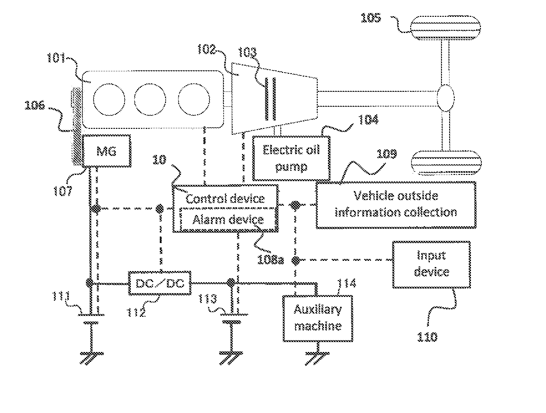
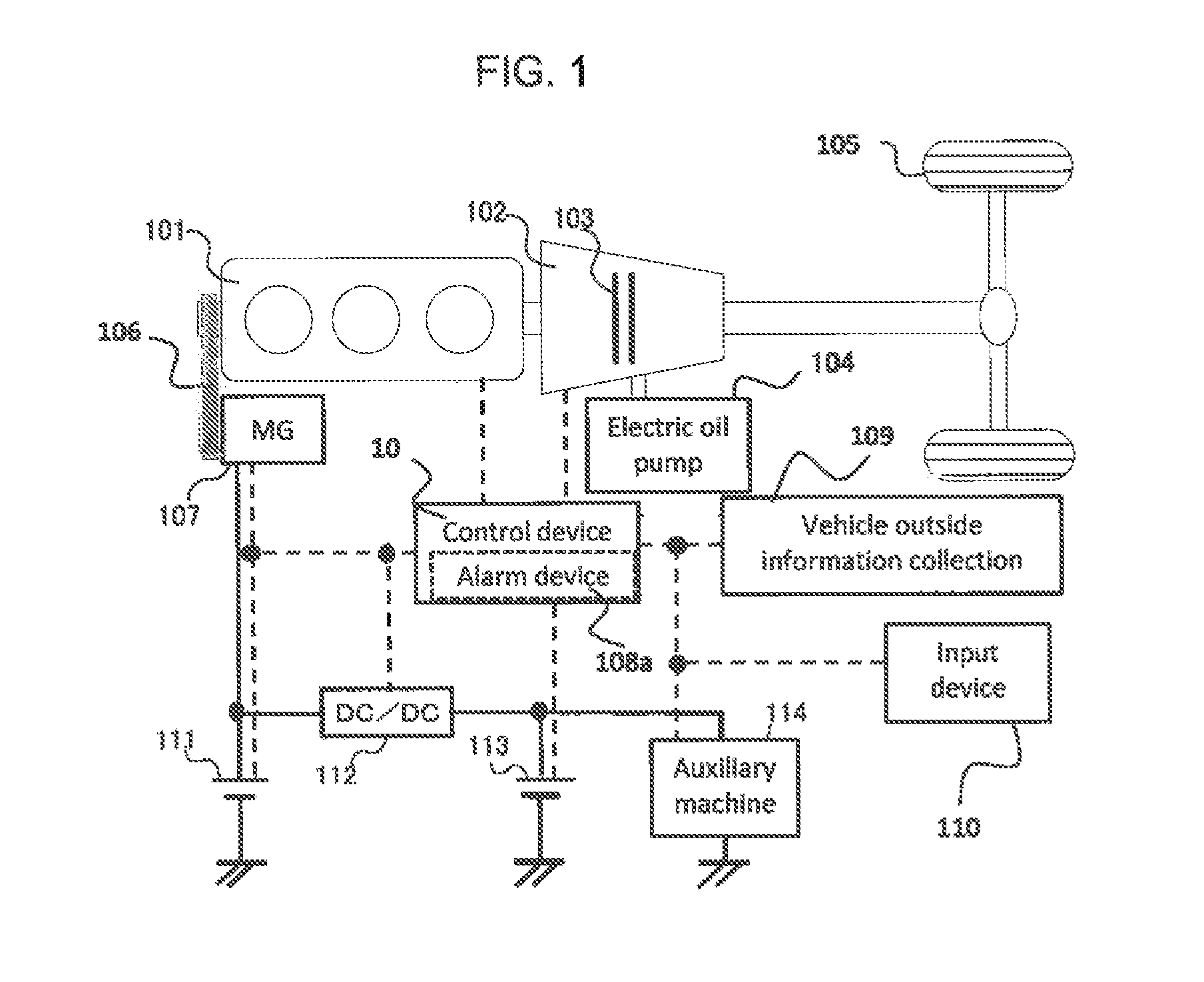
[0021]FIG. 1 is a view schematically showing a configuration of a major portion of a vehicle control apparatus according to a first embodiment of the invention.

[0022]Referring to the drawing, an engine 101, which is a drive source of the vehicle, is connected to a transmission 102 so as to drive drive wheels 105 via a clutch 103 installed inside the transmission 102. Oil is supplied into the transmission 102 by an electric oil pump 104 so that the transmission 102 operates smoothly.

[0023]Also, a motor generator 107 is connected to the engine 101 via a belt 106 and generates power in association with rotations of the engine 101. The respective devices supply a control device 108 with information indicating their own operation states and the operation states are controlled according to outputs of the control device 108. Further, the control device 108 receives input...


PUM


Abstract

An object is to provide a vehicle control apparatus capable of enhancing fuel economy when coasting is performed by disconnecting a clutch disposed between an engine and drive wheels of the vehicle. A travel path and a travel pattern of a vehicle are predicted by a vehicle outside information collection device, such as a navigation system. Also, amounts of fuel consumption by normal traveling and coasting are predicted and compared, so that coasting control is performed in a case where an amount of fuel consumption can be reduced by performing the coasting control.

Description

BACKGROUND OF THE INVENTION[0001]1. Field of the Invention[0002]The present invention relates to a vehicle control apparatus aimed at enhancing fuel economy of a vehicle.[0003]2. Description of the Background Art[0004]Recently, a technique is being developed as a measure taken to enhance fuel economy of an engine-equipped vehicle, according to which coasting is performed by disconnecting a clutch disposed between the engine and drive wheels while the vehicle is moving, so that fuel economy is enhanced by lessening engine drag.[0005]Under the coasting control as above, fuel economy is enhanced by securing a longest possible coasting time. Hence, enhancement of fuel economy depends on determination conditions under which to perform the coasting.[0006]For example, Patent Document 1 discloses that a determination is made so as to select control under which less fuel is consumed depending on whether the coasting control is performed or not when a vehicle is run in a predetermined speed r...

Claims


Application Information

Patent Timeline
IPC IPC(8): B60W10/10B60W10/08F16H59/74
CPCB60W10/10Y10S903/93B60W10/08F16H59/74B60W10/06B60W10/11B60W10/30B60W30/18072B60W50/0097B60W2030/1809B60W2050/143B60W2552/20B60W2556/50Y02T10/40Y02T10/60Y02T10/84
Inventor AKASHI, YOHEITANAKA, HIDEYUKISAITO, HIROYUKI
Owner MITSUBISHI ELECTRIC CORP
Why Eureka
Try Eureka