
Drum type-variable speed drive

a variable speed, drum type technology, applied in the direction of gearing, mechanical control devices, instruments, etc., can solve the problems of increasing operation load and inhibiting smooth shifting operations, and achieve the effects of reducing operation load, easy assembly work, and easy configuration with few parts

Active Publication Date: 2015-04-02
HONDA MOTOR CO LTD
View PDF9 Cites 12 Cited by
  • Summary
  • Abstract
  • Description
  • Claims
  • Application Information

AI Technical Summary

Benefits of technology

The invention aims to reduce friction on a shift drum caused by a lost motion spring. This reduces the effort required to shift gears and makes shifting smoother. A drum type-variable speed drive is used to achieve this.

Problems solved by technology

While the shifter member of the transmission is spline-fitted to a transmission shaft and capable of moving in the axial direction, it is incapable of rotating relative to the transmission shaft, and thus rotates integrally therewith.
This causes rotational friction on the shift drum, which increases the operation load at the time of shifting, and inhibits smooth shifting operations.

Method used


Image

  • Drum type-variable speed drive
  • Drum type-variable speed drive
  • Drum type-variable speed drive

Examples


Embodiment Construction

[0042]Hereinafter, an embodiment of the present invention will be described with reference to FIGS. 1 to 15.

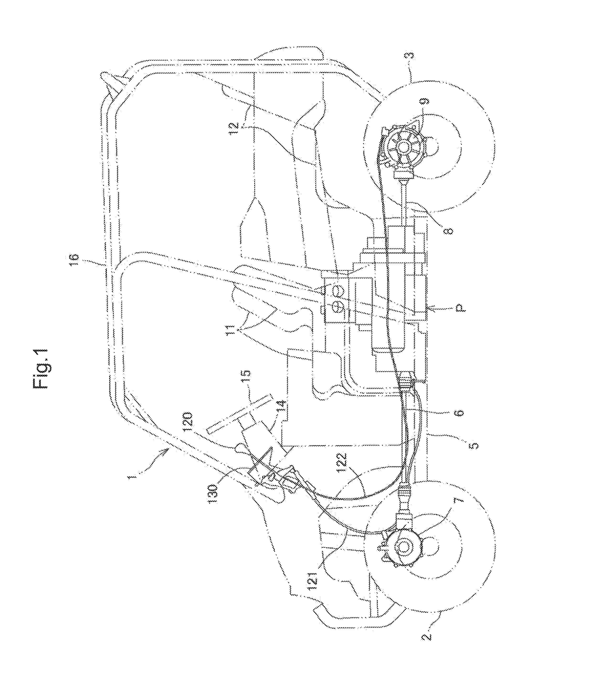
[0043]FIG. 1 shows a side view of a rough terrain vehicle 1 including a power unit according to the embodiment.

[0044]Note that in the description of this specification, front, rear, left, and right directions are based on a normal rule that a direction in which the rough terrain vehicle 1 of the embodiment travels straight is the front.

[0045]Referring to FIG. 1, in the rough terrain vehicle 1, front wheels 2, 2 and rear wheels 3, 3 on which low-pressure balloon tires for rough terrains are mounted are respectively suspended on the front and rear of left and right body frames 5.

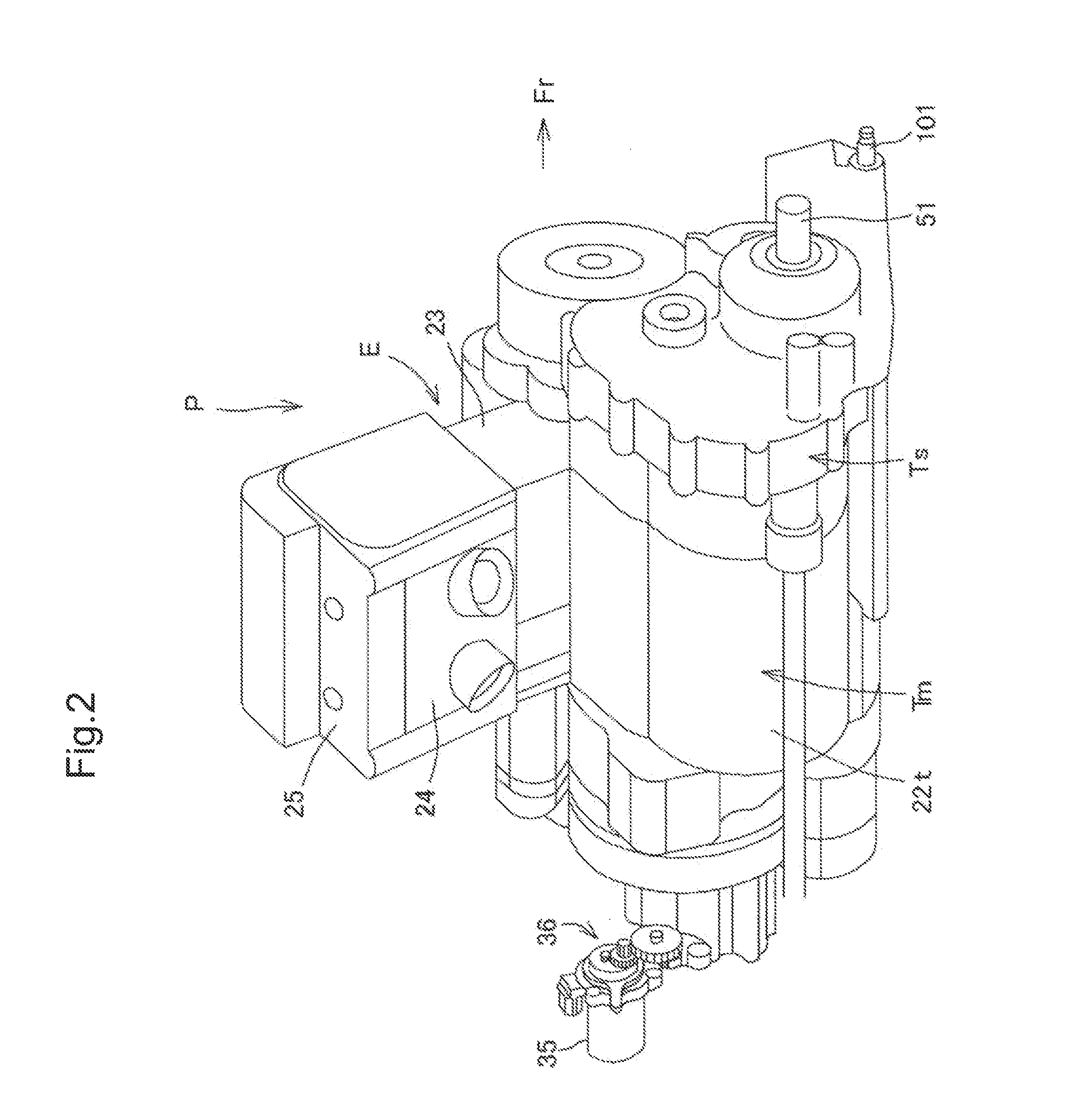
[0046]A power unit P is loaded with a crankshaft 21 of an internal combustion engine E disposed in the longitudinal direction, and an output shaft (transmission driven shaft) 51 of the power unit P protrudes to the front and rear in a longitudinal center position of the body frame 5. A rotative power of ...


PUM


Abstract

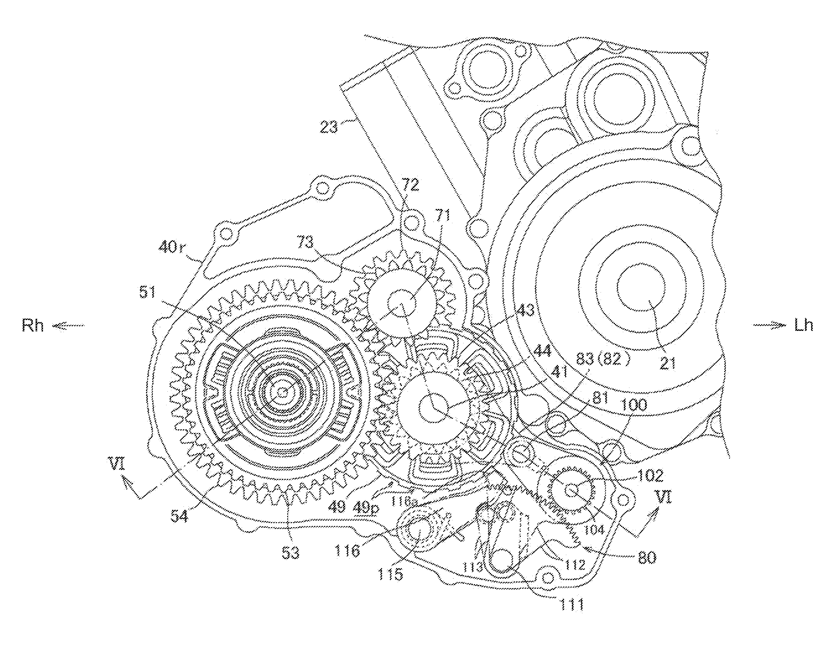
A drum type-variable speed drive wherein a spring bearing member, which is restricted from moving in the axial direction of departing from a shift fork by a locking member fixed to a shift fork shaft, is pivotally supported by the shift fork shaft. A lost motion spring is interposed between the spring bearing member and the shift fork. Movement of the shift fork shaft in the axial direction caused by rotation of a shift drum presses the spring bearing member through the locking member, whereby the spring load of the lost motion spring acts on the shift fork.

Description

BACKGROUND OF THE INVENTION[0001]1. Field of the Invention[0002]The present invention relates to a drum type-variable speed drive in which a shift fork is moved by rotation of a shift drum to shift gears of a transmission.[0003]2. Description of Related Art[0004]A drum type-variable speed drive is generally employed to shift gears of a transmission (see Japanese Patent No. 2515989, for example).[0005]A drum type-variable speed drive disclosed in Japanese Patent No. 2515989 has a general structure, where, with rotation of a shift drum, a shift fork pivotally supported by a shift fork shaft in a slidable manner moves in the axial direction while being guided by a fork guide groove, whereby a shifter member of a transmission engaged with the shift fork is moved in order to drive the gear shift.[0006]While the shifter member of the transmission is spline-fitted to a transmission shaft and capable of moving in the axial direction, it is incapable of rotating relative to the transmission ...

Claims


Application Information

Patent Timeline
IPC IPC(8): F16H59/04F16H3/087
CPCF16H3/087F16H59/042F16H63/18F16H2063/3089Y10T74/20183
Inventor NORITA, KAZUHIROSUMI, HIROMIMITSUBORI, TOSHIMASA
Owner HONDA MOTOR CO LTD
Learn More