Method of Resin Molding and System for Resin Molding

a technology of resin molding and electric wire end, which is applied in the direction of manufacturing tools, application, and connection of coupling devices, can solve the problems of difficult to manage resin thickness, and achieve the effect of easy management of resin thickness

Inactive Publication Date: 2015-04-02
YAZAKI CORP
View PDF3 Cites 11 Cited by
  • Summary
  • Abstract
  • Description
  • Claims
  • Application Information

AI Technical Summary

Benefits of technology

[0030]According to the above terminal fitting, because the protruding part is provided on the terminal fitting, the electric wire end connecting part can be coated with resin of an appropriate thickness without changing the shape of the metal mold, even if the electric wire end connecting part of the terminal fitting is deformed from an appropriate position.
[0031]With the present disclosure, even if the electric wire end connecting part of the terminal fitting is deformed from an appropriate position, an electric wire end connecting part can be coated with resin of an appropriate thickness, and the resin thickness can be easily managed.

Problems solved by technology

In particular, when an interference occurs due to the bending of the terminal fitting 10, because the interference position is uncertain and unpredictable, it is difficult to manage the resin thickness.

Method used


Image

  • Method of Resin Molding and System for Resin Molding
  • Method of Resin Molding and System for Resin Molding
  • Method of Resin Molding and System for Resin Molding

Examples


first embodiment

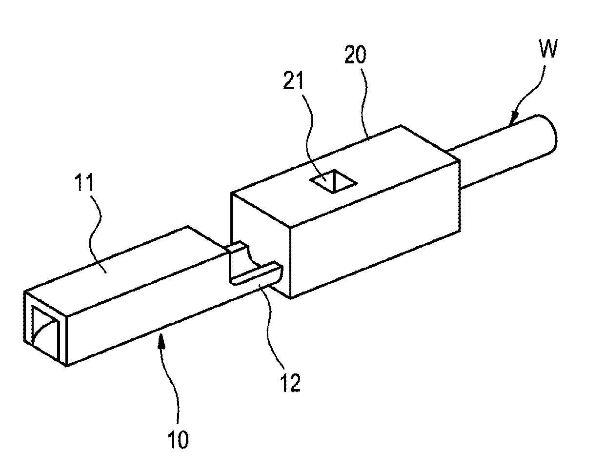
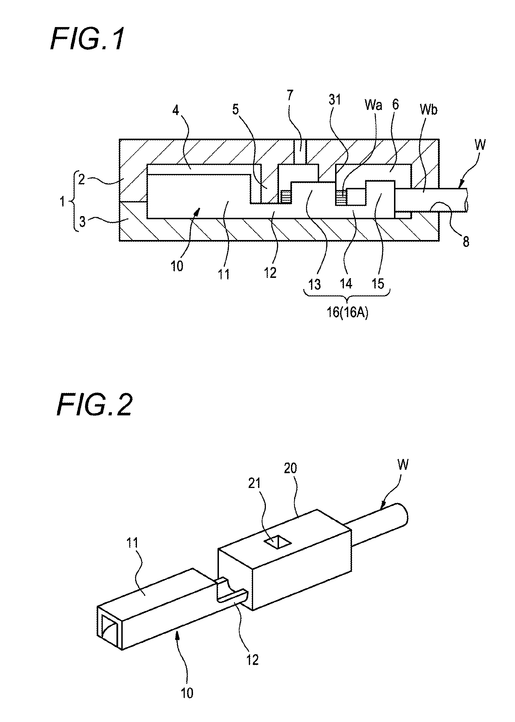
[0048]FIG. 1 is an illustrative figure of a resin molding method of the first embodiment, and is a side sectional view which shows that a terminal fitting is set in a metal mold to resin mold an electric wire end connecting part. FIG. 2 is a perspective view of the terminal fitting after a resin molded part is formed.

[0049]A terminal fitting 10 which is the same as that shown in FIG. 12A is used in the resin molding method of the first embodiment. As shown in FIG. 1, the terminal fitting 10 has an electrical contact part 11 to electrically contact a mating connector terminal at the front part, an electric wire connecting part 16 which is connected to an end portion of an electric wire W at the rear part, and a bridging part 12 arranged between the electrical contact part 11 and the electric wire connecting part 16. The electric wire connecting part 16 has a conductor crimping part 13, which is crimped to a conductor Wa which is exposed by stripping off a sheath Wb of the end portion...

second embodiment and third embodiment

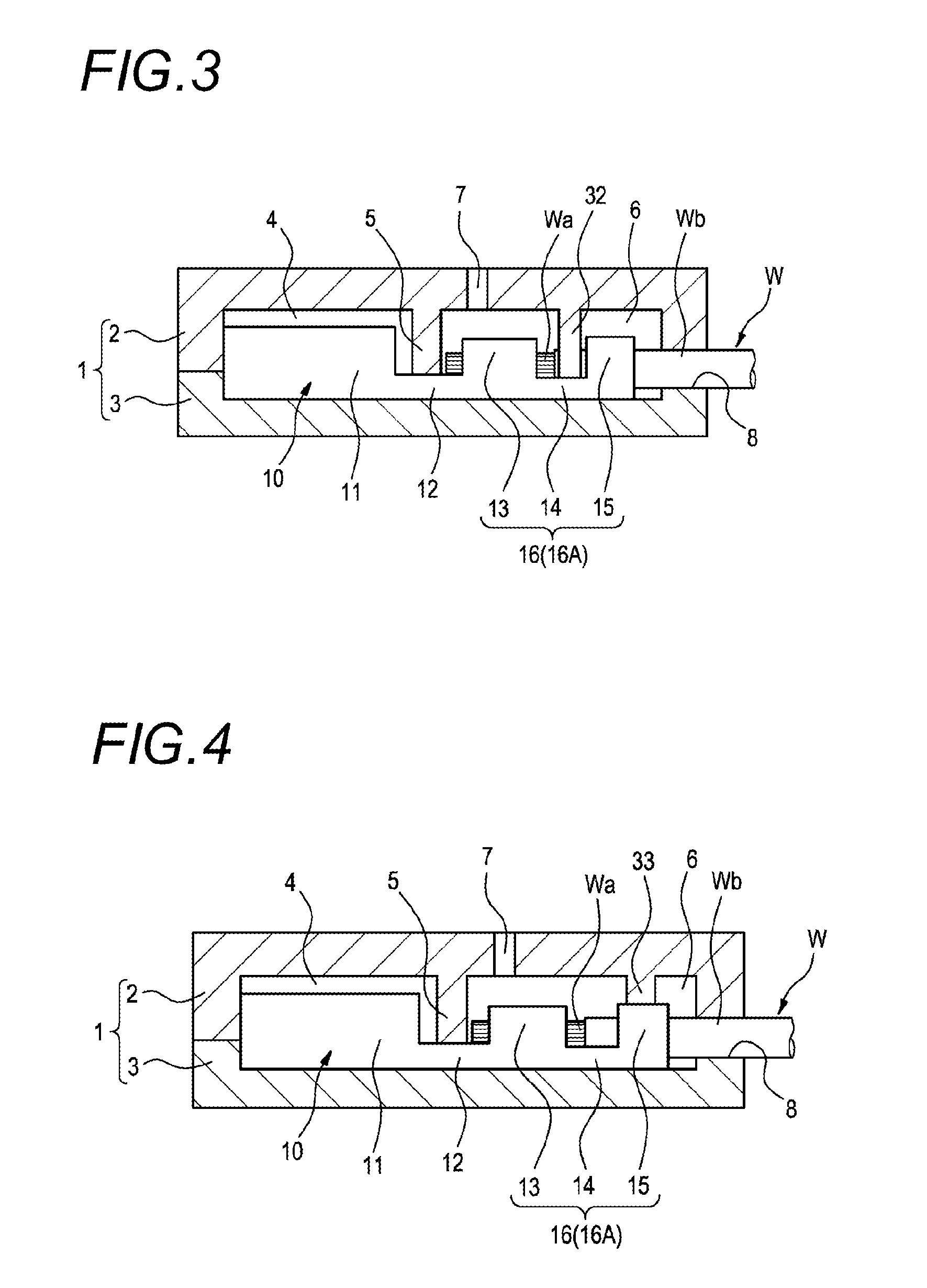
[0054]In the first embodiment, the upper metal mold 2 has the protruding part 31 to interfere with the conductor crimping part 13 of the electric wire connecting part 16, but it is also possible that the upper metal mold 2 has a protruding part 32 at a position where the bridging part 14 of the electric wire connecting part 16 is interfered with the protruding part 21, as in the second embodiment shown in FIG. 3. Also, it is possible that the upper metal mold 2 has a protruding part 33 to interfere with the sheath crimping part 15 of the electric wire connecting part 16, as in the third embodiment shown in FIG. 4.

fourth embodiment

[0055]In the first to the third embodiments described above, a coping method when the terminal fitting 10 is bent upward / downward is described, but the method of this fourth embodiment is a coping method when the electric wire connecting part 16 at the rear part of the terminal fitting 10 is bent leftward and / or rightward relative to the electrical contact part 11 at the front part of the terminal fitting 10 as shown in FIG. 14A. As shown in FIG. 5, two side walls of the lower metal mold 3 in the accommodating space 4 are provided with partition walls 5 which press down the bridging part 12 located at the border between the front part and the rear part of the terminal fitting 10 to maintain positions and define the front end of the cavity 6.

[0056]The right and left inner side walls of the cavity 6 are provided with protruding parts 34 which interfere with the electric wire connecting part 16 and correct the electric wire connecting part 16 into an appropriate position (appropriate f...


PUM

PropertyMeasurementUnit
pressing forceaaaaaaaaaa
corrosion resistanceaaaaaaaaaa
electrolytic corrosionaaaaaaaaaa

Abstract

A terminal fitting includes an electric wire end connecting part that crimps an end portion of an electric wire, and a protruding part that is provided on the electric wire end connecting part. The protruding part interferes with an inner wall which forms a cavity of a main body of a metal mold when the electric wire end connecting part being deformed from an appropriate position is set in the cavity, and corrects the electric wire end connecting part into the appropriate position by a pressing force which occurs due to the interference of the protruding part and the inner wall of the cavity.

Description

CROSS REFERENCE TO RELATED APPLICATIONS[0001]This application is a continuation of PCT application No. PCT / JP2013 / 066769, which was filed on Jun. 12, 2013 based on Japanese Patent Application (No. P2012-134132) filed on Jun. 13, 2012, the contents of which are incorporated herein by reference.BACKGROUND OF THE INVENTION[0002]1. Field of the Invention[0003]The present invention relates to a method of resin molding an electric wire end connecting part which is formed by crimping an electric wire connecting part that is provided at a rear part of a terminal fitting to an end portion of an electric wire, a system having a metal mold and a terminal fitting used to perform the method.[0004]2. Description of the Related Art[0005]When a terminal fitting is connected to an end portion of an electric wire, it is usual that an electric wire connecting part provided at the rear part of the terminal fitting is crimped to the end portion of the electric wire. When the terminal fitting is crimped ...

Claims


Application Information

Patent Timeline
Patent Type & Authority Applications(United States)
IPC IPC(8): B29C45/14B29C45/26
CPCB29C45/14065B29C45/14819B29C45/26B29L2031/36B29K2905/00B29K2101/00B29K2995/0058B29C2045/14131B29C45/14426B29C45/14467B29C45/14639H01R4/185H01R13/405H01R13/52H01R43/24H01R4/18H01R4/182H01R4/183H01R4/184
Inventor SATO, KEI
Owner YAZAKI CORP
Why Eureka
Try Eureka