Pitch bearing

Active Publication Date: 2015-04-02
SIKORSKY AIRCRAFT CORP
View PDF9 Cites 6 Cited by
  • Summary
  • Abstract
  • Description
  • Claims
  • Application Information

AI Technical Summary

Problems solved by technology

The magnitude of the loads acting on the bearings and the space constraints of the rotor configurations present a

Method used


Image

  • Pitch bearing
  • Pitch bearing
  • Pitch bearing

Examples


Embodiment Construction

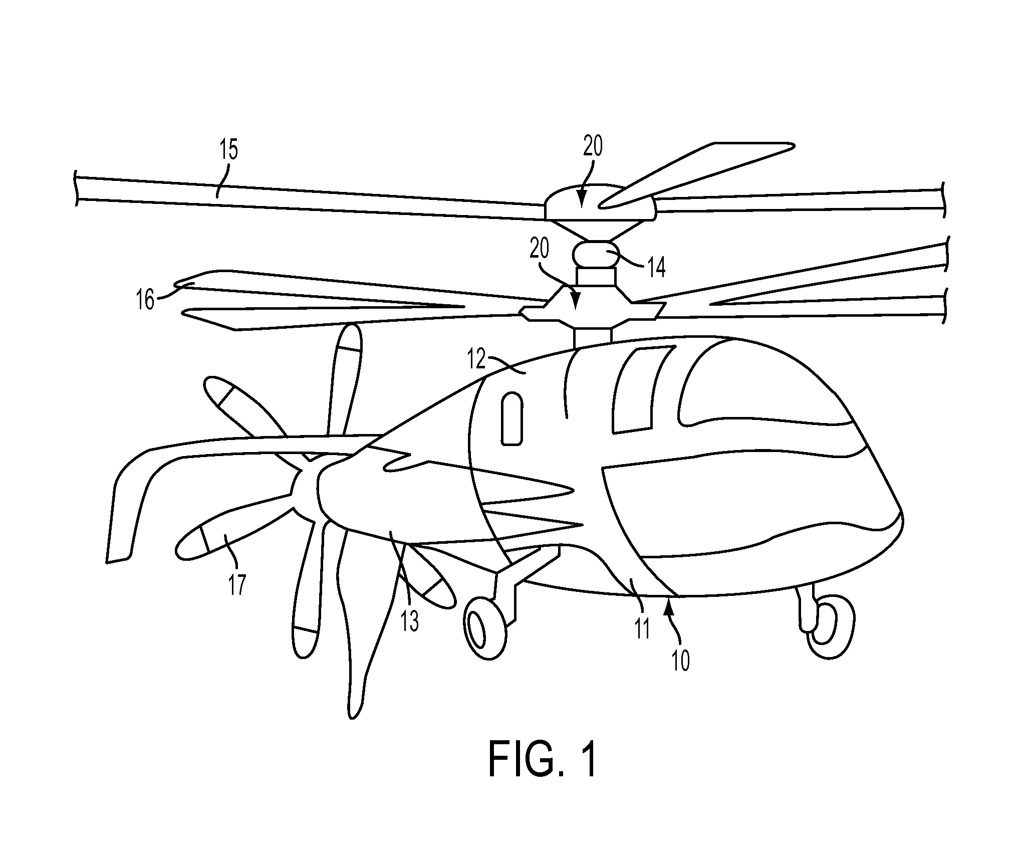
[0015]With reference to FIG. 1, a rotormachine 10 is provided. The rotormachine 10 includes a fuselage 11 that is formed to define an interior cabin in which a pilot and passengers may be situated. The fuselage 11 includes a pylon section 12 at a top portion thereof and a tail section 13 at a trailing end thereof The pylon section 12 is supportive of a main rotor shaft 14 that is rotatable about its longitudinal or vertical axis relative to the fuselage 11. The main rotor shaft 14 is respectively coupled to coaxial main rotor blades 15 and 16, which rotate with the main rotor shaft 14 to provide a lift force for the rotormachine 10. The tail section 13 is supportive of a propeller shaft (not shown) that is rotatable about a longitudinal axis thereof relative to the fuselage 11 and in a plane defined transversely with respect to a rotational plane of the main rotor shaft 14. The propeller shaft is coupled to a pusher propeller 17, which rotates with the propeller shaft, to provide th...


PUM


Abstract

A pitch bearing for connecting first and second articles is provided. The first article includes a first curved outer surface and the second article includes a second curved outer surface opposite the first curved outer surface. The pitch bearing includes an axisymmetric structure interposed between the first and second curved outer surfaces. The axisymmetric structure includes compliant layers and stabilizing layers interleaved between the compliant layers. The compliant layers and the stabilizing layers proximate to the first article haves a curvature matching that of the first curved outer surface. The compliant layers and the stabilizing layers proximate to the second article have a curvature matching that of the second curved outer surface. A shear stiffness of each of the stabilizing layers is greater than a shear stiffness of each of the compliant layers.

Description

BACKGROUND OF THE INVENTION[0001]The subject matter disclosed herein relates to a pitch bearing and, more particularly, to a reverse curvature compliant pitch bearing.[0002]In current configurations of main rotors of helicopters or rotormachines, a significant percentage of the loads acting on the blades are transmitted to the central hub through elastomeric bearings. In addition to this load transference, these bearings allow the blades to pitch in response to pilot input through the various control systems on board. The magnitude of the loads acting on the bearings and the space constraints of the rotor configurations present a significant challenge to designing a set of bearings and a connecting block that have acceptable component lives.BRIEF DESCRIPTION OF THE INVENTION[0003]According to one aspect of the invention, a pitch bearing for connecting first and second articles is provided. The first article includes a first curved outer surface and the second article includes a seco...

Claims


Application Information

Patent Timeline
IPC IPC(8): B64C27/35F16C27/06
CPCF16C27/06B64C27/35
Inventor HUNTER, DAVID H.PARSONS, ERIC S.NUSSENBLATT, ERIC LUCIENCASEY, RYAN THOMAS
Owner SIKORSKY AIRCRAFT CORP
Why Eureka
Try Eureka