Image blur correction apparatus, lens apparatus, image pickup apparatus, method of controlling image blur correction apparatus, and non-transitory computer-readable storage medium

a technology of image blur correction and optical system, which is applied in the direction of color television details, television system details, television systems, etc., can solve the problems of unavoidable recording of blur motion images caused by a decrease in image blur correction performance, and the inability to disclose a method of keeping continuity of control, etc., to achieve satisfactory blur correction effect, continuous control, and smooth control of optical system

Active Publication Date: 2015-04-09
CANON KK
View PDF3 Cites 24 Cited by
  • Summary
  • Abstract
  • Description
  • Claims
  • Application Information

AI Technical Summary

Benefits of technology

[0009]The present invention provides an image blur correction apparatus capable of appropriately driving and continuously and smoothly controlling correction optical systems and thereby of achieving a satisfactory blur correction effect even in motion image shooting, a lens apparatus, an image pickup apparatus, a method of controlling the image blur correction apparatus, and a non-transitory computer-readable storage medium.

Problems solved by technology

However, since the image blur correction apparatus disclosed in JP 2002-250952 has a configuration intended for still image shooting, the apparatus has the following problem when applied to motion image shooting.
However, it does not disclose a method of keeping continuity of the control when the focal length varies due to a zooming operation or when the correction optical system is switched.
Therefore, in the motion image shooting, an unnatural image motion caused by the switching of the correction optical system used for the image blur correction and a wide-blur motion image caused due to a decrease in an image blur correction performance are unavoidably recorded.

Method used


Image

  • Image blur correction apparatus, lens apparatus, image pickup apparatus,  method of controlling image blur correction apparatus, and non-transitory computer-readable storage medium
  • Image blur correction apparatus, lens apparatus, image pickup apparatus,  method of controlling image blur correction apparatus, and non-transitory computer-readable storage medium
  • Image blur correction apparatus, lens apparatus, image pickup apparatus,  method of controlling image blur correction apparatus, and non-transitory computer-readable storage medium

Examples


first embodiment

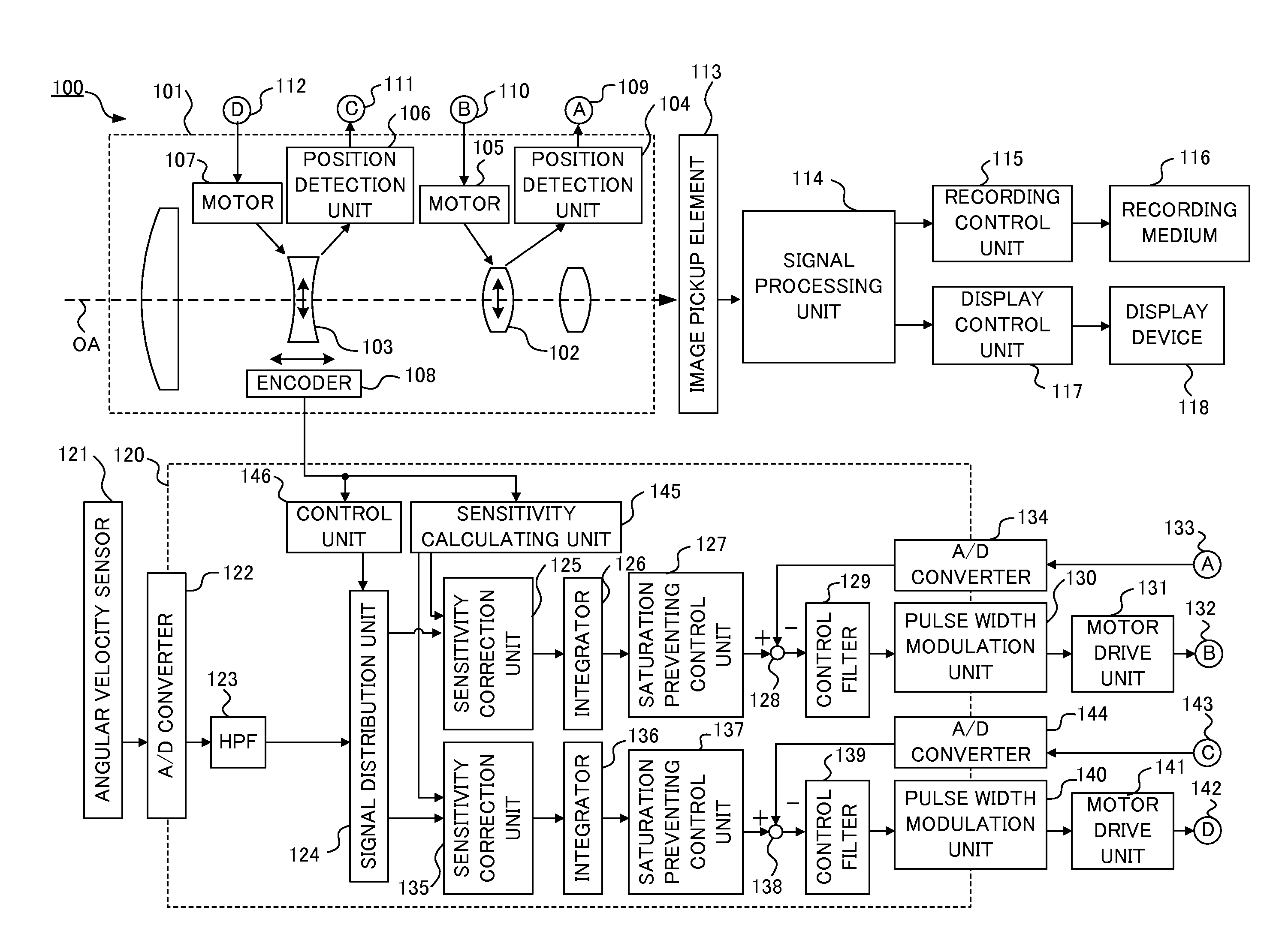
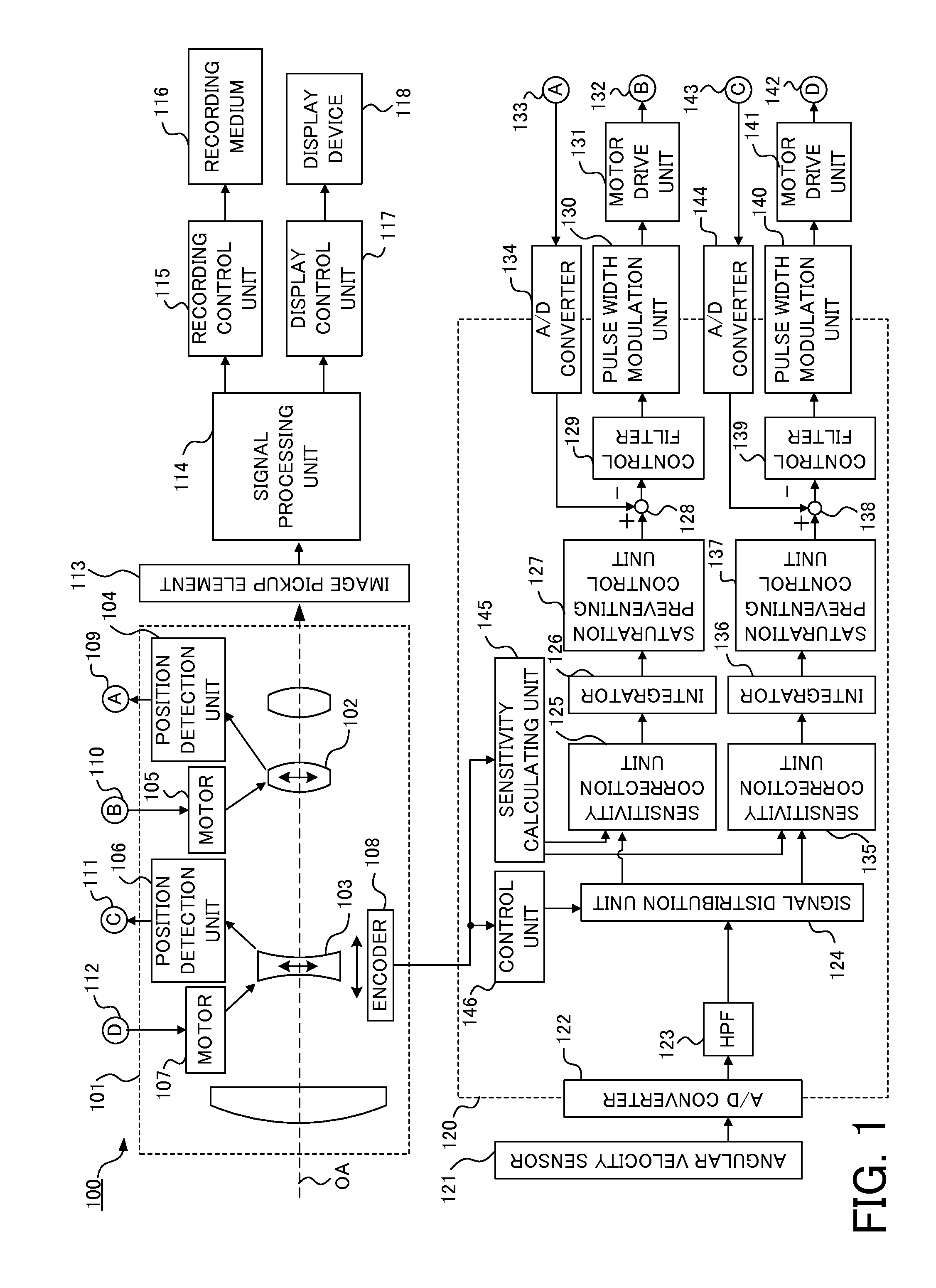
[0027]First of all, referring to FIG. 1, a description will be given of a configuration of an image pickup apparatus including an image blur correction apparatus (image stabilizer) in the first embodiment of the present invention. FIG. 1 is a block diagram illustrating a configuration of an image pickup apparatus 100 in this embodiment. The image pickup apparatus 100 includes the image blur correction apparatus which uses a first optical correction unit (a shift lens 102) and a second optical correction unit (a magnification varying lens 103) to optically correct a blur in an image (a shot image). The image blur correction apparatus of this embodiment includes, at least, an angular velocity sensor 121, a microcomputer 120, and motor drive units 131 and 141.

[0028]While a digital video camera as an example of the image pickup apparatus 100 will be described in this embodiment, applications are not limited to this. This embodiment is applicable to, for example, arbitrary image pickup a...

second embodiment

[0059]Next, the second embodiment of the present invention will be described. Since this embodiment can be achieved with the same configuration as that of the image pickup apparatus 100 described with reference to FIG. 1, a description thereof will be omitted.

[0060]Referring to FIG. 5, a signal distribution unit in this embodiment will be described. FIG. 5 is a block diagram of a signal distribution unit 124a in this embodiment. The signal distribution unit 124a in this embodiment separates a vibration signal detected by an angular velocity sensor 121 into a plurality of frequency bands different from each other (two frequency bands of a high-frequency band and a low-frequency band). That is, the signal distribution unit 124a performs a frequency-band separation calculation for the vibration signal to separate the vibration signal into a first separated vibration signal and a second separated vibration signal. Thereafter, the signal distribution unit 124a outputs two vibration signa...

third embodiment

[0071]Next, the third embodiment of the present invention will be described. In the first and second embodiments, the vibration signal of the image pickup apparatus 100 detected by the angular velocity sensor 121 is separated into the two signals and the two correction optical systems are then controlled based on the two signals to perform the hand-shake correction. On the other hand, in this embodiment, one of the correction optical systems is driven based on a signal different from information on the vibration of the image pickup apparatus 100.

[0072]The signal different from the information on the vibration of the image pickup apparatus 100 is, for example, a drive signal for tracking-controlling a position of a face of a person (an object) detected from a captured image such that the position is located near a center of a screen. The control is performed with one of the correction optical systems so as to track the position of the face of the person (the object), with the other p...


PUM


Abstract

An image blur correction apparatus includes a vibration detection unit configured to detect vibration information of the image blur correction apparatus to output a vibration signal, a signal separation unit configured to separate the vibration signal into a first vibration signal and a second vibration signal, a first sensitivity correction unit configured to correct an amplitude of the first vibration signal, a second sensitivity correction unit configured to correct an amplitude of the second vibration signal, a first drive unit configured to drive the first optical correction unit based on an output signal from the first sensitivity correction unit, and a second drive unit configured to drive the second optical correction unit based on an output signal from the second sensitivity correction unit.

Description

BACKGROUND OF THE INVENTION[0001]1. Field of the Invention[0002]The present invention relates to an image blur correction apparatus which uses a plurality of correction optical systems to correct an image blur.[0003]2. Description of the Related Art[0004]Conventionally, image pickup apparatuses have been known which use two correction optical systems to correct an image blur. Such an image pickup apparatus has been increasingly required to be capable of performing high-magnification zooming in which a focal length largely varies. In optical image blur correction, where a ratio between a displacement of each correction optical system and that of an image is referred to as an “eccentricity sensitivity k”, the eccentricity sensitivity k is represented by a function containing a focal length f and a photographing magnification 3. A displacement dL of each correction optical system is represented by the following Expression (1) by using the eccentricity sensitivity k and a correction ang...

Claims


Application Information

Patent Timeline
Patent Type & Authority Applications(United States)
IPC IPC(8): H04N5/232
CPCH04N5/23258H04N5/23287H04N23/6812H04N23/687
Inventor WATANABE, TAKESHI
Owner CANON KK
Why Eureka
Try Eureka