Device for Connecting a Centerless Auger to a Rotatable Member

a technology of centerless augers and rotatable parts, which is applied in the direction of controlling members, liquid fuel engine components, non-positive displacement fluid engines, etc., can solve the problems of unusable “waste” or residual toner, the auger has its own drawbacks, and the toner put on the photoconductive drum does not get transferred to the media sh

Active Publication Date: 2015-04-09
LEXMARK INT INC
View PDF4 Cites 10 Cited by
  • Summary
  • Abstract
  • Description
  • Claims
  • Application Information

AI Technical Summary

Benefits of technology

[0014]A coupling device for retaining a helical auger on a rotating member according to one example embodiment includes an elongated body insertably positionable within an inner diameter of the auger between the inner diameter of an end of the auger and the rotating member. A groove is formed on an outer surface of the elongated body having a shape complementary a helical flight of the auger. A snap-fit engagement feature on an inner surface of the elongated body enables removable coupling of the retaining member to the rotating member.

Problems solved by technology

Image forming devices such as printers, copiers, facsimile machines, and the like, produce unusable “waste” or residual toner as a byproduct of an electrophotography (EP) process.
However, due to inefficiencies within the image transfer process, all of the toner put on the photoconductive drum does not get transferred to the media sheet or ITM.
However, each of these types of augers has its own drawbacks.
However, the problem with the plastic molded augers is that these are most often resistant to bending and can only transfer waste toner in straight channels.
A barrier for practical implementation of metal wire augers is the need for a metal drive shaft used to connect the auger with its drive source.
However, metal drive shafts add significant cost to the overall auger design, decreasing its likelihood for use in mass production.
However, securing or coupling the metal auger to the plastic drive shaft is a significant obstacle in designing a plastic drive shaft.
Further, the size of the coupling mechanism is also generally very small, making it difficult to transmit the torque needed without risk of breakage.
Unfortunately, this method is very sensitive to manufacturing parameters and is a much more expensive alternative to hand assembly.
For example, it is difficult to clamp onto the auger with an injection molding machine without damaging the auger and without allowing molten plastic to leak out along the auger wire.
Further, the metal auger may not adhere sufficiently to the plastic drive shaft and can be easily disconnected from the plastic drive shaft by unscrewing the auger from the plastic drive shaft.

Method used


Image

  • Device for Connecting a Centerless Auger to a Rotatable Member
  • Device for Connecting a Centerless Auger to a Rotatable Member
  • Device for Connecting a Centerless Auger to a Rotatable Member

Examples


Embodiment Construction

[0029]In the following description, reference is made to the accompanying drawings where like numerals represent like elements. The embodiments are described in sufficient detail to enable those skilled in the art to practice the present disclosure. It is to be understood that other embodiments may be utilized and that process, electrical, and mechanical changes, etc., may be made without departing from the scope of the present disclosure. Examples merely typify possible variations. Portions and features of some embodiments may be included in or substituted for those of others. The following description, therefore, is not to be taken in a limiting sense and the scope of the present disclosure is defined only by the appended claims and their equivalents.

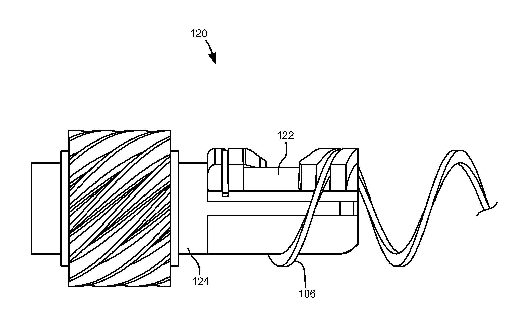
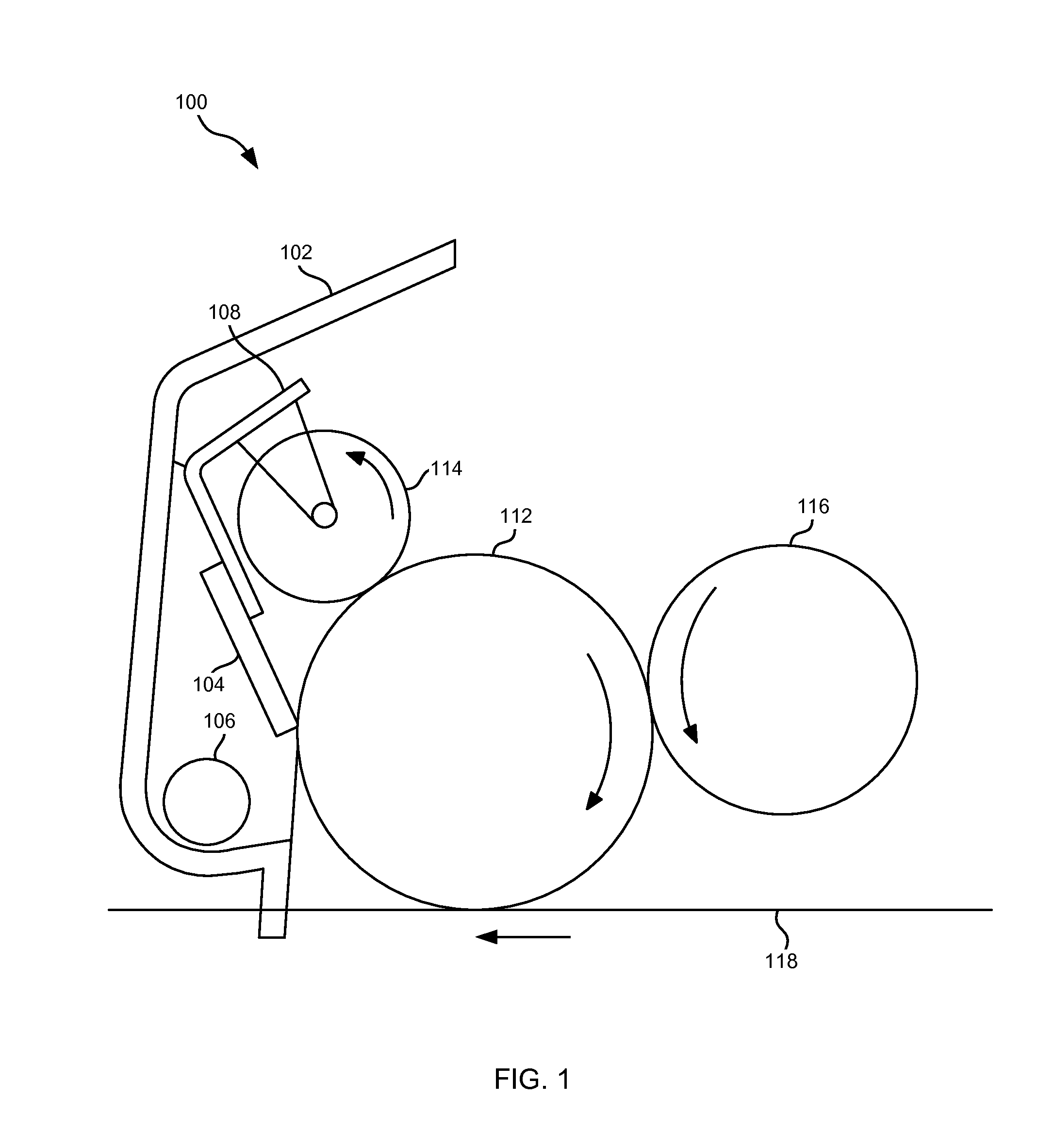
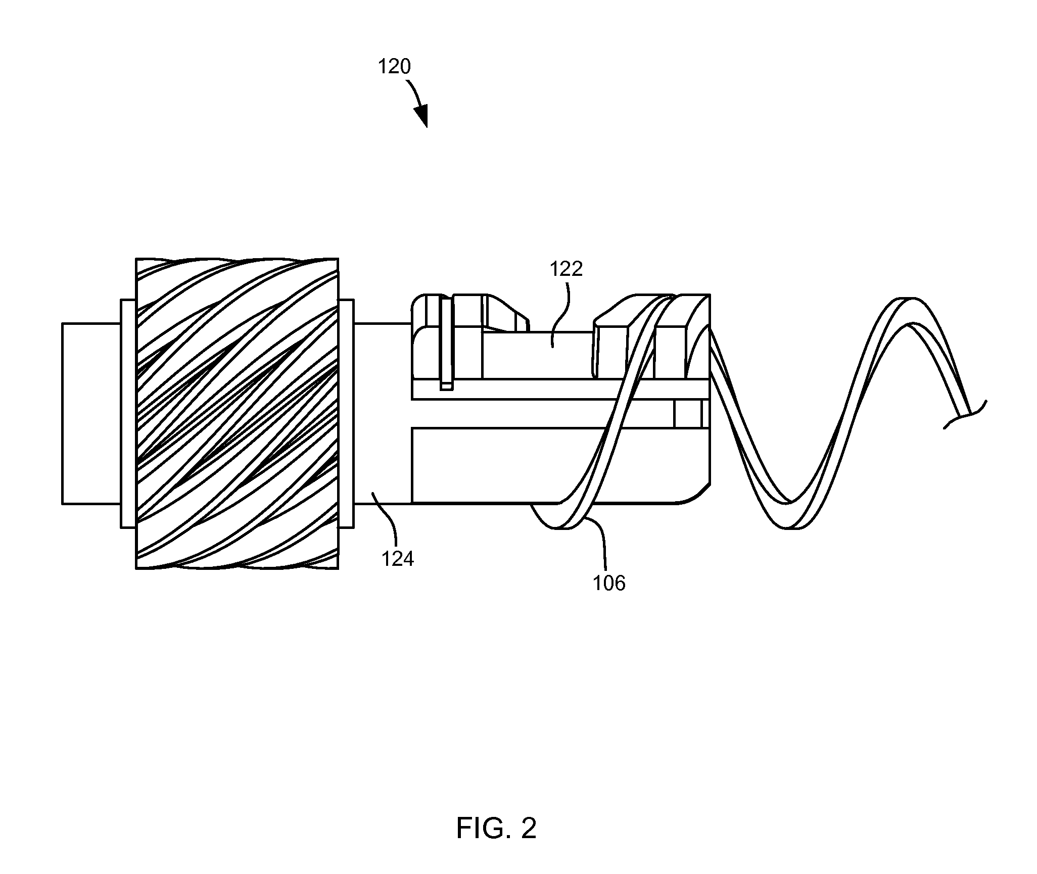
[0030]FIG. 1 illustrates a cleaner assembly 100 including a cleaner housing 102, a cleaner blade 104, and an auger 106 disposed within the cleaner housing 102. A bracket member 108 is attached to the cleaner housing 102 to hold cleane...


PUM


Abstract

An auger assembly according to one example embodiment includes an auger having a helical flight extending along a longitudinal axis. The auger has a central opening running along the longitudinal axis. The auger has an end that includes at least a portion of a turn having substantially zero pitch. A retaining member has a body including a groove on an outer surface of the body. The groove has a shape complementary to the helical flight at the end of the auger. At least a portion of the end of the auger is retained within the groove. A rotatable coupling member extends along the longitudinal axis. At least a portion of the rotatable coupling member is positioned within the central opening of the auger and presses the outer surface of the retaining member against an inner diameter of the end of the auger.

Description

CROSS REFERENCES TO RELATED APPLICATIONS[0001]None.BACKGROUND[0002]1. Field of the Invention[0003]The present invention relates generally to augers and more particularly to a device for connecting a centerless auger to a rotatable member.[0004]2. Description of the Related Art[0005]Image forming devices such as printers, copiers, facsimile machines, and the like, produce unusable “waste” or residual toner as a byproduct of an electrophotography (EP) process. Ideally, all of the toner that is picked up by a photoconductive drum such as from a developer roll in the case of a single component development process or a magnetic roll in the case of a dual component development process would be transferred onto a media sheet (or an intermediate transfer member (ITM) in the case of a two-step toner transfer process). However, due to inefficiencies within the image transfer process, all of the toner put on the photoconductive drum does not get transferred to the media sheet or ITM. This resi...

Claims


Application Information

Patent Timeline
Patent Type & Authority Applications(United States)
IPC IPC(8): G03G21/10F16D1/02
CPCG03G21/105G03G2215/0833F16D1/02F16D1/108F16B2200/10G03G15/0891
Inventor REIDHAAR, GLEN ALAN
Owner LEXMARK INT INC
Why Eureka
Try Eureka