Special cast-in-place pile drilling machine for road bridge construction

A technology for bridge construction and cast-in-place piles, applied in bridges, bridge construction, rotary drilling rigs, etc., can solve problems such as affecting the performance of the filling column, the inclination of the drill bit, and the unbalanced force.

Pending Publication Date: 2020-04-17
江苏中车城市发展有限公司 +1
View PDF0 Cites 9 Cited by
  • Summary
  • Abstract
  • Description
  • Claims
  • Application Information

AI Technical Summary

Problems solved by technology

[0004] In view of the above problems, the present invention aims to provide a special cast-in-situ pile drilling machine for road and bridge construction, to solve the problem that the common drilling machine is ti

Method used


Image

  • Special cast-in-place pile drilling machine for road bridge construction
  • Special cast-in-place pile drilling machine for road bridge construction
  • Special cast-in-place pile drilling machine for road bridge construction

Examples


Embodiment Construction

[0020] Below by embodiment and in conjunction with accompanying drawing, the present invention will be further described:

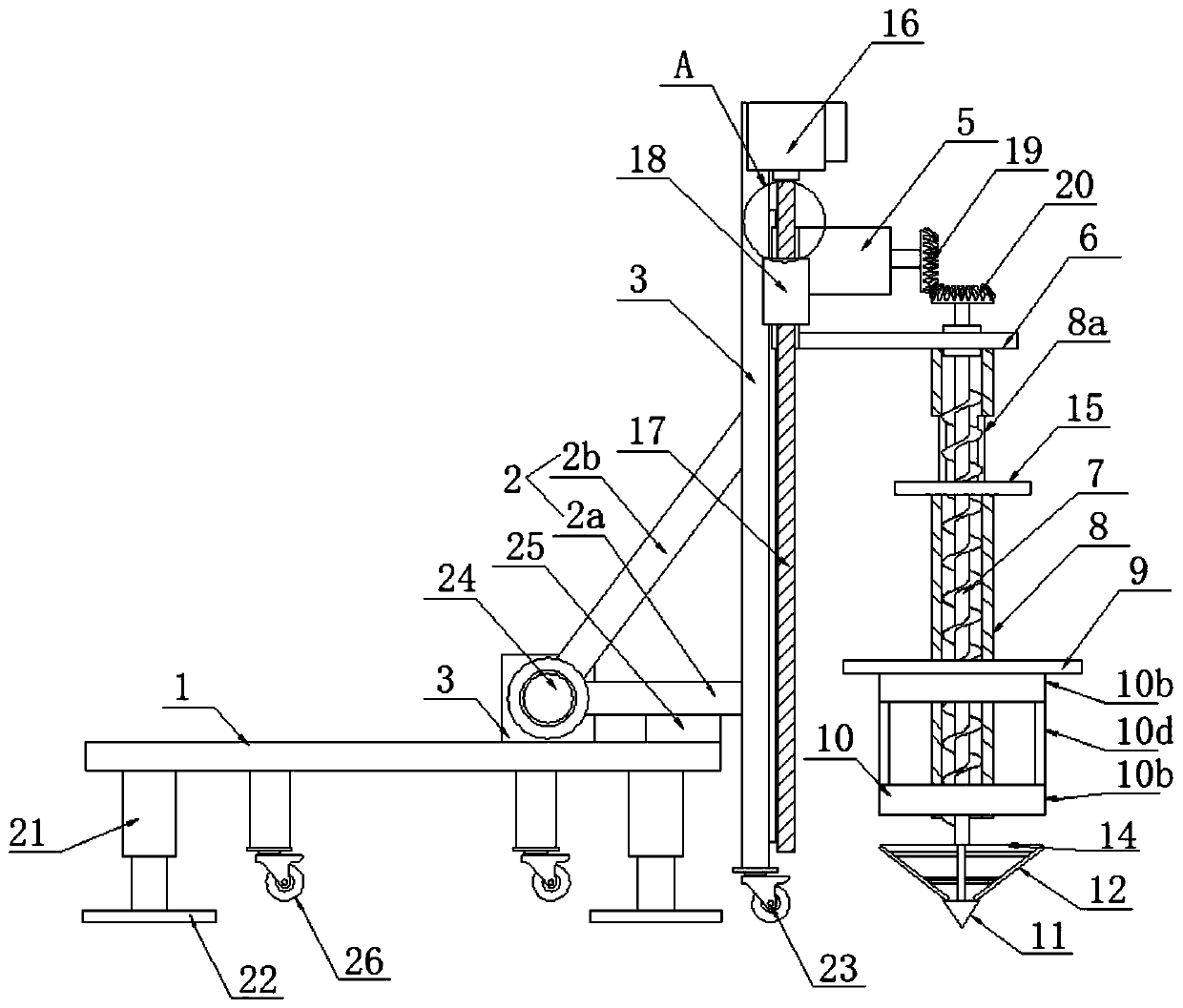
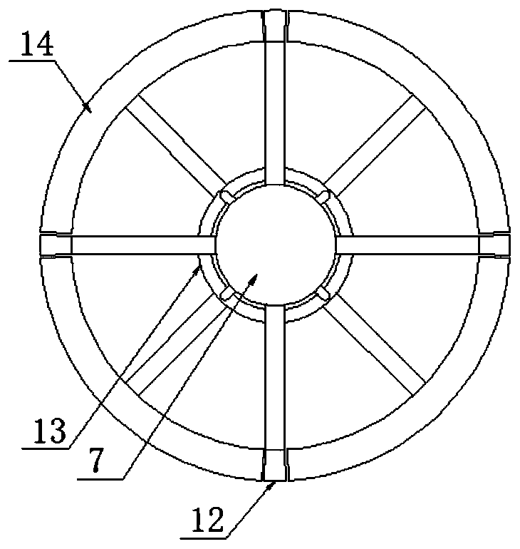
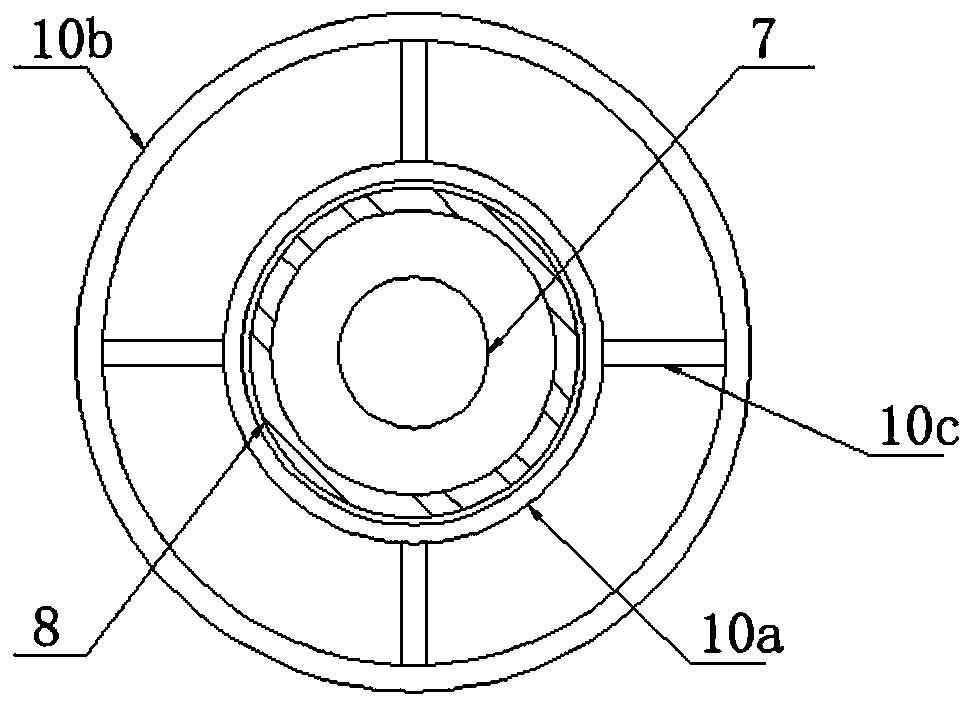
[0021] Such as figure 1 — Figure 4 As shown, a special cast-in-situ pile drilling machine for road and bridge construction is mainly composed of a fixed frame 1, a turning frame 2, a rotating plate 3, a sliding plate 4, a first motor 5, a supporting plate 6, a conveying auger 7, and a limit cylinder 8 , the first baffle plate 9, positioning cylinder 10, drill bit 11, alloy blade 12, moving ring 13, arc plate 14, second baffle plate 15, second motor 16, screw mandrel 17, threaded cylinder 18, first bevel gear 19 , second bevel gear 20, four hydraulic cylinders 21, support plate 22, support runner 23, fixed rotating shaft 24, backing plate 25, moving wheel 26 are formed.

[0022] The left side of the rotating plate 3 is connected to the fixed mount 1 through the turning frame 2, so that the rotating plate 3 can be placed on the fixed mount 1 horizontally...


PUM


Abstract

The invention discloses a special cast-in-place pile drilling machine for road bridge construction, which is characterized in that a rotating plate not only can be horizontally arranged above a fixingframe and but also can be vertically arranged on the outer side of the fixing frame after being overturned by 90 degrees; a sliding plate, a first motor, a supporting plate, a conveying auger, a second motor and a limiting cylinder are mounted on the right side of the rotating plate; a soil outlet is formed in the side wall of the upper part of the limiting cylinder; an orifice positioning baffleassembly sleeves the outer wall of the lower part of the limiting cylinder in a clearance manner; the lower end of the conveying auger extends out of the limiting cylinder; a drill bit is fixedly connected to the bottom end of the conveying auger; when a moving ring descends to the lowest position, all arc plates and alloy blades are just spliced into a complete panel, and when the moving ring ascends to the highest position, all the arc plates are separated from the alloy blades so as to form a gap allowing soil to pass through between the arc plates and the alloy blades. The drilling machine solves the problems that the drill bit inclines due to unbalanced stress of a common drilling machine, the construction is affected, there are a lot of impurities at the bottom when the drill bit istaken out, and the performance of a filling column is affected.

Description

technical field [0001] The invention belongs to the technical field of drilling equipment, in particular to a drilling machine for cast-in-situ piles specially used for road and bridge construction. Background technique [0002] Road bridges are generally composed of several parts such as roadbed, road surface, bridge, tunnel engineering and traffic engineering facilities. When building roads and bridges, it is necessary to use a drilling machine to drill holes first, and then make cast-in-place piles. Cast-in-situ piles are piles made by forming holes in place and pouring concrete or reinforced concrete. The commonly used ones are: (1) Bored cast-in-place piles: use auger drilling rigs, submersible drilling rigs, etc. to form holes and pour concrete on the spot to form piles. There is no vibration and no soil squeezing during construction, but the settlement of the piles is slightly larger; Cast-in-place pile with pipe: sink the steel pipe with reinforced concrete pile sho...

Claims


Application Information

Patent Timeline
IPC IPC(8): E01D21/00E21B3/02E21B7/02E21B15/00
CPCE01D21/00E21B3/02E21B7/02E21B15/00
Inventor 钱栋栋薛金峰朱春柏刘小荣王振赛那明望张光耀
Owner 江苏中车城市发展有限公司
Why Eureka
Try Eureka