Method for connecting poles of battery cells

a battery cell and connecting pole technology, applied in the field of connecting poles of battery cells, can solve the problems of stranded wires that cannot be secured, and achieve the effects of simple and cost-effective connection, good electrical properties, and good electrical properties

Inactive Publication Date: 2015-04-09
ROBERT BOSCH GMBH
View PDF2 Cites 16 Cited by
  • Summary
  • Abstract
  • Description
  • Claims
  • Application Information

AI Technical Summary

Benefits of technology

[0005]The present invention is based on the object of refining a method for connecting poles of battery cells according to the description herein in such a way that a particularly cost-effective connection is achieved between the individual battery cells, with good electrical properties. This object is achieved according to the present invention in a method for connecting poles of battery cells having the features described herein in that the stranded wire in the terminal area of an electric pole of the battery cell is connected in a welding area using a laser weld. In other words, this means that the method according to the present invention only still has one stranded wire as a single connecting element as the connecting element, so that method steps which relate to the connection of the stranded wire to (plate-shaped) elements for connecting the stranded wire to the battery poles according to the related art may be saved. A particularly simple and cost-effective connection between the poles of the battery cells is thus made possible.
[0008]For this reason, it may be provided that during the formation of the laser weld between the stranded wire and the pole of the battery cell, the laser beam is moved oscillatingly in the weld area. An oscillating movement is understood as a back-and-forth movement of the laser beam which may take place in principle both in an advance direction of the laser beam, and also perpendicularly or at an angle to the advance direction. In particular the air enclosures between the individual wires of the stranded wire may be expelled to some extent by the oscillating movement of the laser beam, so that a particularly good heat transfer and heat input are generated by the laser beam, which results in a good fusion of the material of the stranded wire and the pole of the battery cell and therefore a high-quality welded joint.
[0009]In a variant of the movement of the laser beam, it is provided that the laser beam is moved oscillatingly perpendicular to the advance direction of the laser beam. With relatively short process times, a relatively broad weld seam is thus produced, which has a low electrical resistance due to its large area.
[0010]To improve the welded joint, it may additionally be provided that the laser beam passes over the weld seam multiple times. In particular relatively uniform heating of the welded area may thus take place, because thermal tension peaks are avoided or reduced during the production of the weld seam.
[0012]With regard to the device, the welded joints, which are produced by the laser beam, may be manufactured particularly precisely and easily if the laser beam is moved by an optical device. This optical device ensures the required advance movement of the laser beam, on the one hand, and at the same time (if provided) ensures the oscillating movement of the laser beam, on the other hand.

Problems solved by technology

Due to the configuration of the stranded wire, in the case of which it is typically made of a wire braid, which is made of a plurality of individual wires, air enclosures are situated between the individual wires, which impair a secure connection between the stranded wire or the stranded wire material and the pole of the battery cell and also the fusion of the material.

Method used


Image

  • Method for connecting poles of battery cells
  • Method for connecting poles of battery cells

Examples


Embodiment Construction

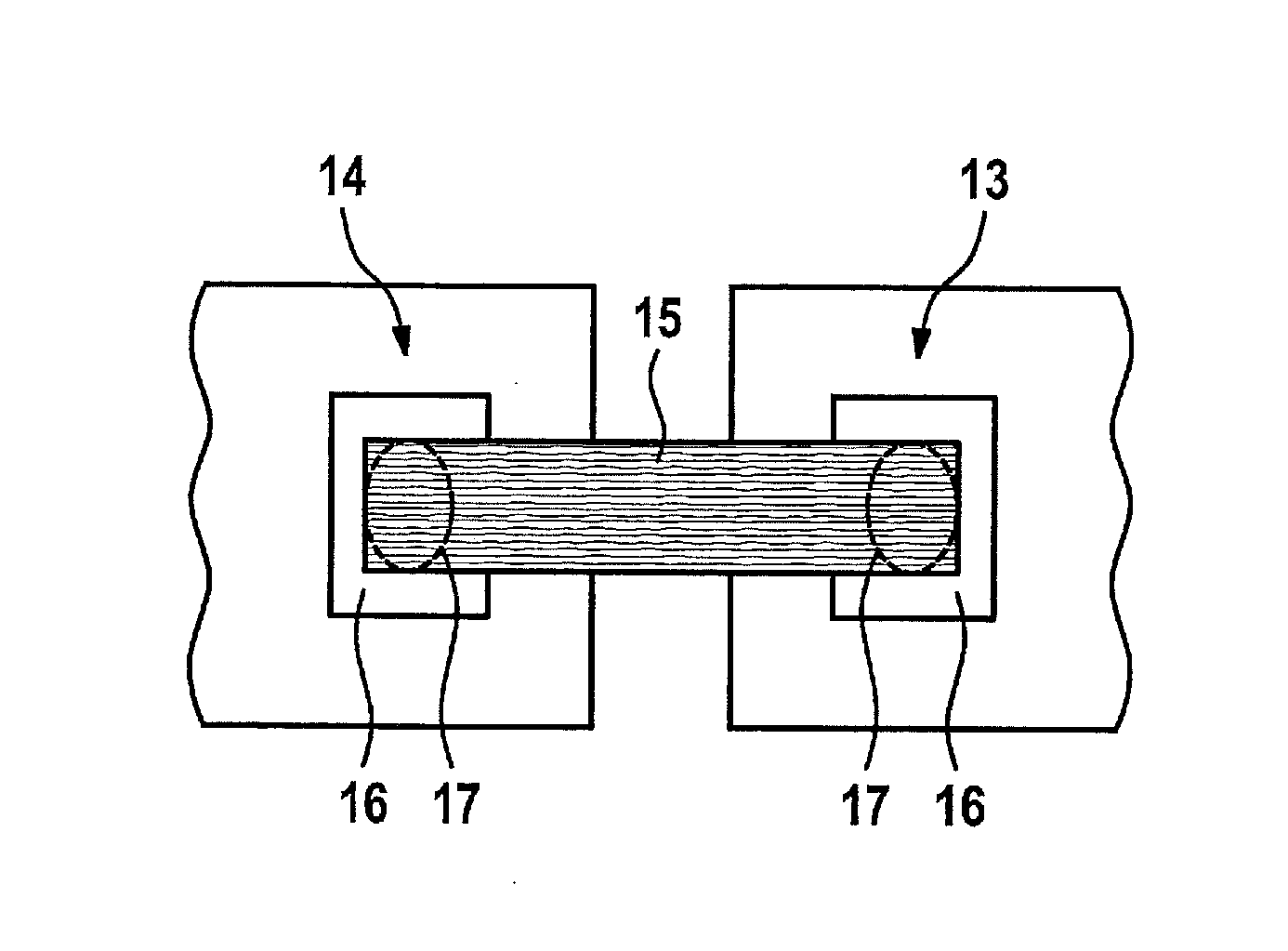
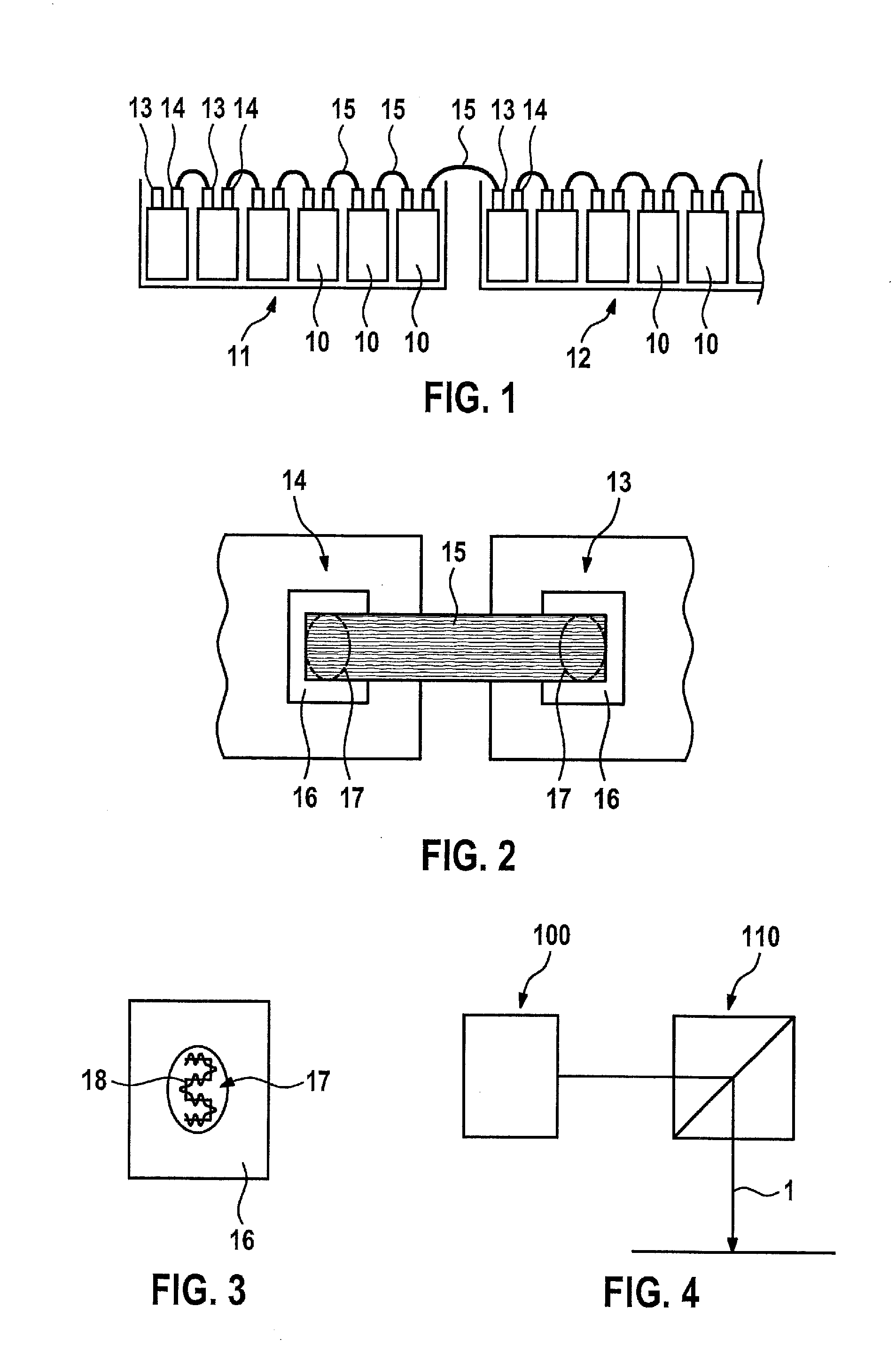
[0019]FIG. 1 shows two battery modules 11, 12 situated adjacent to one another as an example, as they may be, but not restrictively, used as a component of a power supply unit in a hybrid vehicle. Of course, it may also be provided that such a power supply unit includes more than two battery modules 11, 12. Each of battery modules 11, 12 contains multiple battery cells 10, which may be configured identically, it being presumed as an example and in simplified form that six battery cells 10 are situated adjacent to one another in battery module 11. In addition, it is explained that such a power supply unit in a hybrid vehicle may include a total of approximately one hundred battery cells 10, which are allocated to corresponding battery modules 11, 12.

[0020]Each battery cell 10 has a positive pole 13 and a negative pole 14. It is presumed as an example that individual battery cells 10 in battery modules 11, 12 are connected to one another in series, i.e., in each case one positive pole...


PUM

PropertyMeasurementUnit
areaaaaaaaaaaa
poweraaaaaaaaaa
electricalaaaaaaaaaa

Abstract

A method for connecting poles of two battery cells includes using a connecting element, which is configured as a stranded wire and connects the poles of the battery cells to one another. The stranded wire is connected directly to a pole of a battery cell in a welding area with a laser beam for forming a laser beam weld.

Description

FIELD OF THE INVENTION[0001]The present invention relates to a method for connecting poles of battery cells.BACKGROUND INFORMATION[0002]In recent time, the connection of poles of battery cells has come more and more into focus, in particular due to the use of battery cells in hybrid vehicles. One object is to electrically connect the single cells, which are typically arranged inside a battery module, to one another and in turn to assemble or connect the battery modules on their part to one another to form an overall power source. In particular, it is desirable that, for example, mechanical loads on the individual battery cells in the battery modules or on the battery modules do not result in an impairment of the connection between the individual poles of the battery cells or between the battery modules. Therefore, an electrical connection between the battery poles which is elastic to some extent is desirable.[0003]For this reason, for example, a method for connecting poles of batter...

Claims


Application Information

Patent Timeline
Patent Type & Authority Applications(United States)
IPC IPC(8): H01M2/20B23K26/08B23K26/32H01M50/528H01M50/516
CPCH01M2/206B23K26/0807B23K26/3213H01R11/288H01R43/0221B23K26/32B23K26/082B23K26/21B23K2103/08B23K2103/10B23K2103/12Y02E60/10H01M50/516
Inventor BANTEL, CHRISTOPHNEUBERT, HEINZRAMSAYER, REINERGUENTER, FRIEDHEIMDUDZIAK, SONJA
Owner ROBERT BOSCH GMBH
Why Eureka
Try Eureka