Separate connection device for grounding electrical equipment comprising a plurality of separate electrical components

a technology of electrical equipment and separate electrical components, which is applied in the direction of coupling device connections, photovoltaics, heat collector mountings/supports, etc., can solve the problems of a large number of connection accessories, a large number of wiring operations, and a relatively long intervention time on site, so as to eliminate or reduce significantly the wiring requirements, short intervention time, and convenient use

Active Publication Date: 2015-05-19
MOBASOLAR
View PDF11 Cites 10 Cited by
  • Summary
  • Abstract
  • Description
  • Claims
  • Application Information

AI Technical Summary

Benefits of technology

[0006]The present invention aims to offer a solution for this problem that will allow guaranteeing the quality of the electrical connection of the grounding of each photovoltaic panel in a very short intervention time, without having to entrust a qualified person with this work, while eliminating or reducing significantly the wiring requirements, by means of a simple, cost-effective, easy-to-use, reliable and versatile connecting device.

Problems solved by technology

This wiring operation can of course be carried out only by an authorized electrician and requires a relatively long intervention time on site.
This intervention is all the more complicated to carry out as the equipment is installed at a high location, for example on a roof.
Furthermore, the wiring operation requires great electrical wire lengths and a large number of connection accessories.
In addition, the quality of the connection of the electrical wires by means of terminals and screws in holes made in the metal frame of the panels is not guaranteed, since this metal frame can be covered with a layer of an electrically insulating finish cover such as anodic oxidation, enameling or similar.
However, its shape does not allow it to become embedded in the metal material of both the metal frame and the supporting structure like a harpoon, and without possibility to remove it without using a tool.
Consequently, the efficiency of the electrical contact is not guaranteed over time.

Method used


Image

  • Separate connection device for grounding electrical equipment comprising a plurality of separate electrical components
  • Separate connection device for grounding electrical equipment comprising a plurality of separate electrical components
  • Separate connection device for grounding electrical equipment comprising a plurality of separate electrical components

Examples


Embodiment Construction

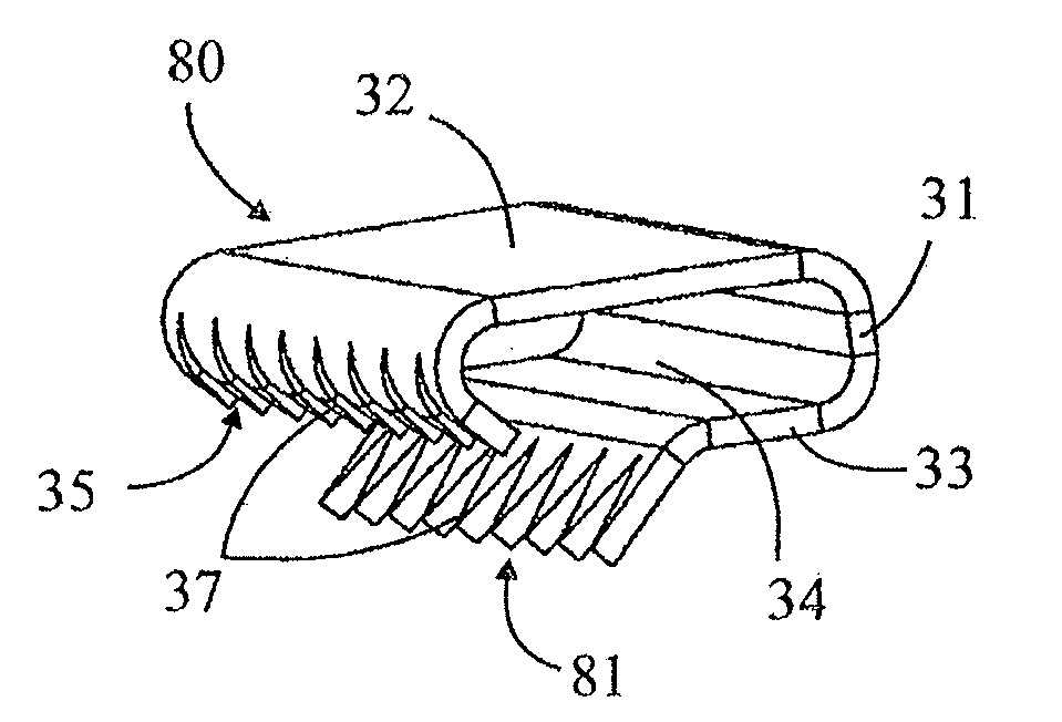
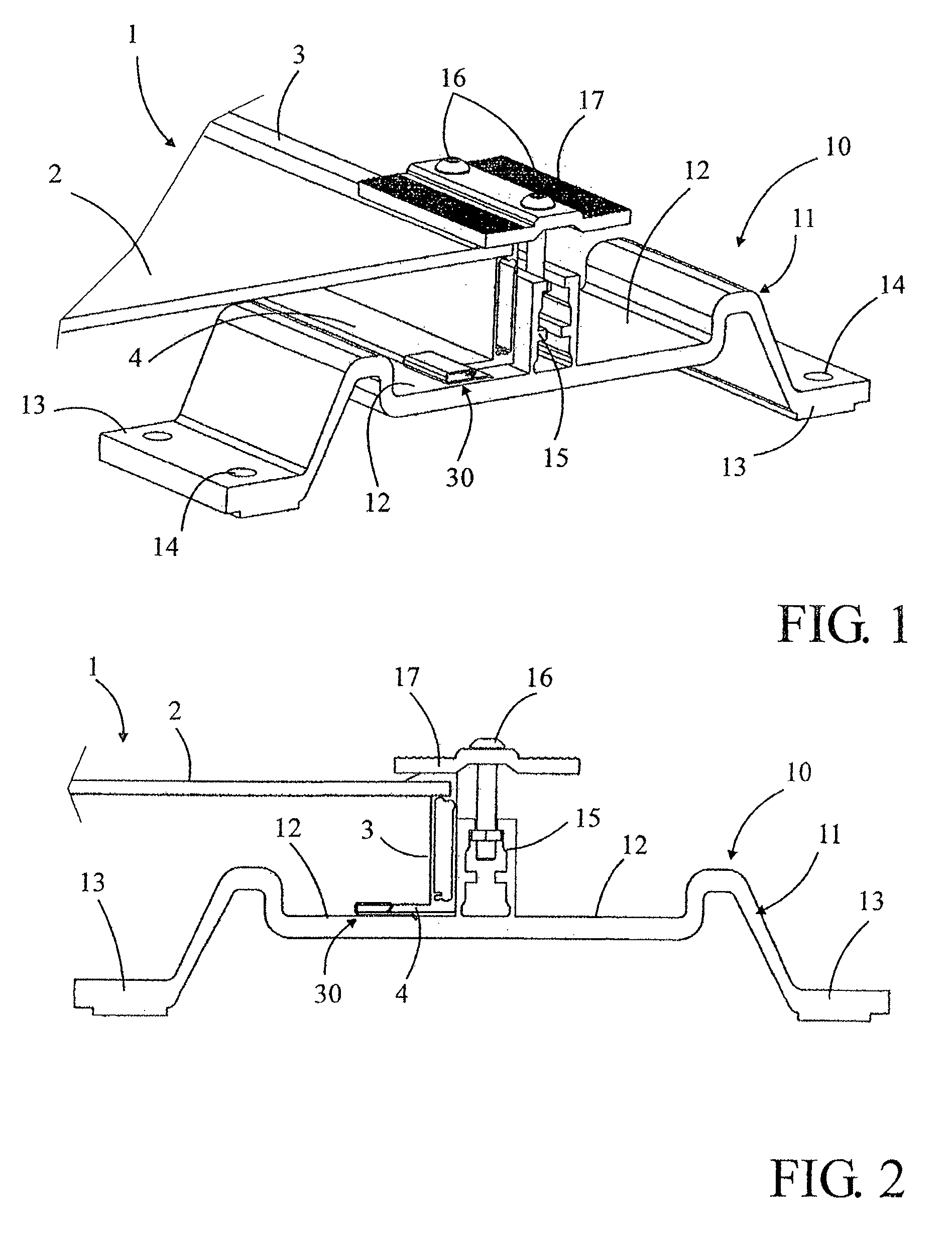
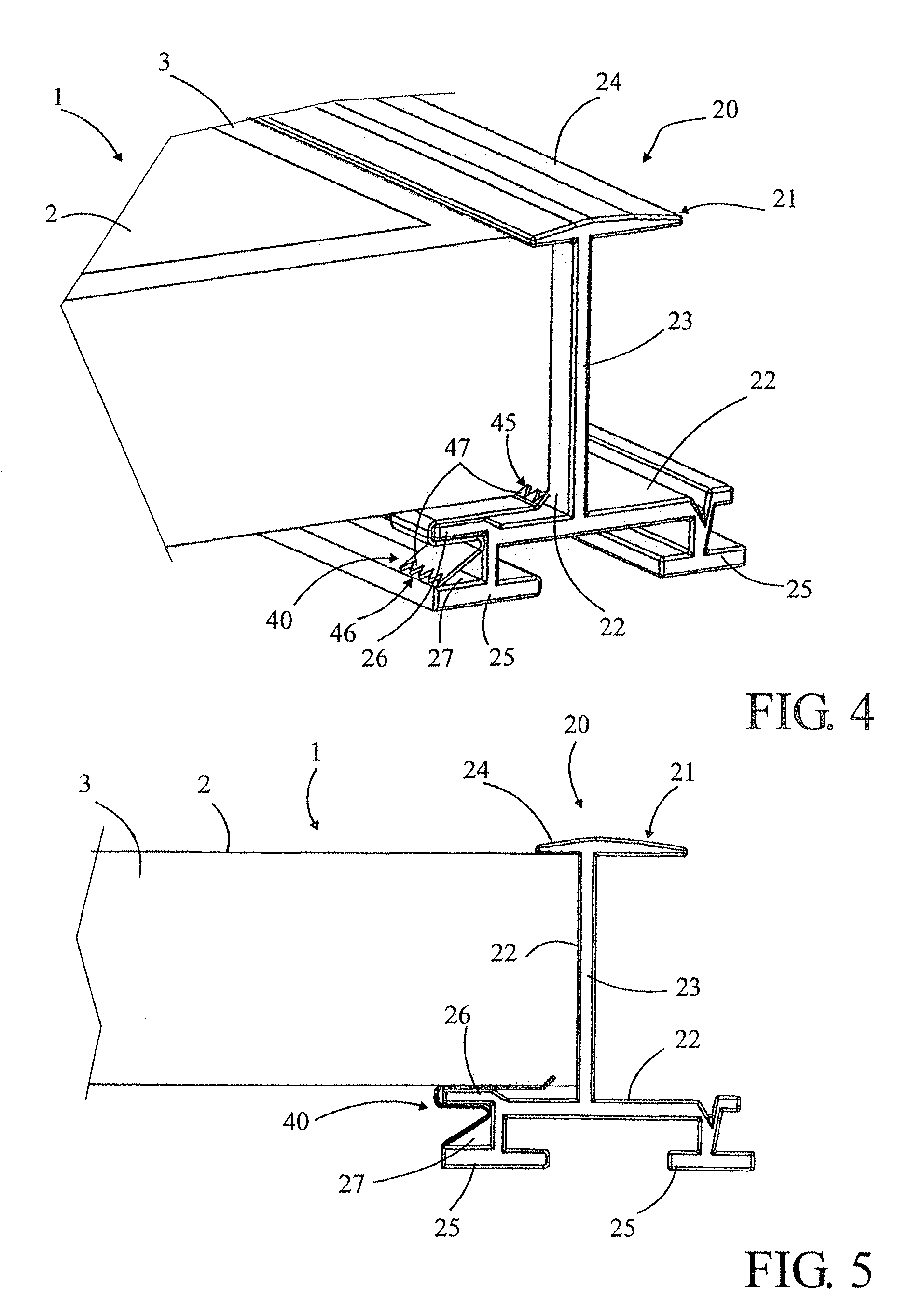
[0026]The following description relates to electrical equipment comprising a plurality of photovoltaic panels 1. Of course, the connection device according to the invention applies to any type of separate electrical components requiring grounding, such as thermal panels, hybrid thermal / photovoltaic panels or similar, as well as to the inverters or micro-inverters belonging to said equipment and to any other metallic surface of an electrical equipment requiring grounding.

[0027]The photovoltaic panels 1 comprise in a known way, and in reference to the figures, a plate with photovoltaic cells 2 surrounded by a metal frame 3 that allows fastening them onto any kind of supporting structure 10, 20, 50, on the floor or at a high location, on fixed or movable structures, etc. This metal frame 3 can be made of raw, anodized, enameled, or similar, aluminum, or also in any other equivalent material, raw, treated or covered with a protection and / or finish layer. These photovoltaic panels 1 are ...


PUM


Abstract

A separate connection device (40) intended to be inserted between a metal frame (3), of an electrical component (1), and a metal supporting structure (20) in order to connect, electrically and separately, the frame to the supporting structure. The connection device (40) comprises a metal blade manufactured from spring steel which comprises two self-connecting end areas (45, 46) arranged in separate planes and comprising a set of sharp teeth (47) arranged in order to be embedded within the metal material and formed on a folded section of the metal blade so that the sets of teeth (37, 47) extend in opposite directions and in planes intended to intersect the planes of the frame (3) and of the supporting structure (20) when the connection device is mounted.

Description

[0001]This application is a National Stage completion of PCT / IB2012 / 000446 filed Mar. 9, 2012, which claims priority from French patent application serial no. 11 / 52023 filed Mar. 11, 2011.FIELD OF THE INVENTION[0002]The present invention relates to a separate connection device for grounding electrical equipment comprising a plurality of separate electrical components, in particular photovoltaic panels, each electrical component being delimited by a metal frame arranged so as to be fastened on a metal supporting structure, said separate connection device being intended to be inserted between said metal frame of each electrical component and said metal supporting structure for electrically and separately connecting said metal frame of each electrical component to said metal supporting structure, said separate connection device comprising a metal blade comprising at least one closed fold arranged so as to form a plug-on assembly area.BACKGROUND OF THE INVENTION[0003]In all photovoltaic...

Claims


Application Information

Patent Timeline
Patent Type & Authority Patents(United States)
IPC IPC(8): H05K5/02H05F3/02F24J2/52H01L31/042H01R4/64
CPCH05F3/02H01R4/64F24J2/5207F24J2/5258H02S20/00Y02E10/50Y02E10/47F24S25/632F24S25/35F24S25/636
Inventor KELLER, MARC
Owner MOBASOLAR
Why Eureka
Try Eureka