Method of manufacturing surgical template positioning device

a positioning device and template technology, applied in the field of surgical implants, can solve the problems of still limited by the outline of the conventional positioning pin, parameter reading error, and difficulty for dentists to further correct the template based, and achieve the effect of reducing the inevitable deviation

Active Publication Date: 2015-04-09
TAIWAN IMPLANT TECH
View PDF4 Cites 7 Cited by
  • Summary
  • Abstract
  • Description
  • Claims
  • Application Information

AI Technical Summary

Benefits of technology

[0007]A primary object of the present invention is to provide a surgical template positioning device and a method of manufacturing the same, which uses three non-collinear points to determine a plane, so as to actually repre

Problems solved by technology

However, even though the tooth computed tomography (CT) machine can provide an effective surgical simulated environment, such as effectively displaying the height and thickness of the alveolar bone and the actual distribution locations of nerves and blood vessels and exchanging different viewing angles for surveying the predefined position of tooth implant, it is still limited by the outline of the conventional positioning pins.
When the positioning pins are not parallel to each other, the actual relative position will not be ab

Method used


Image

  • Method of manufacturing surgical template positioning device
  • Method of manufacturing surgical template positioning device
  • Method of manufacturing surgical template positioning device

Examples


Embodiment Construction

[0039]The structure and the technical means adopted by the present invention to achieve the above and other objects can be best understood by referring to the following detailed description of the preferred embodiments and the accompanying drawings. Furthermore, directional terms described by the present invention, such as upper, lower, front, back, left, right, inner, outer, side, longitudinal / vertical, transverse / horizontal, etc., are only directions by referring to the accompanying drawings, and thus the used directional terms are used to describe and understand the present invention, but the present invention is not limited thereto.

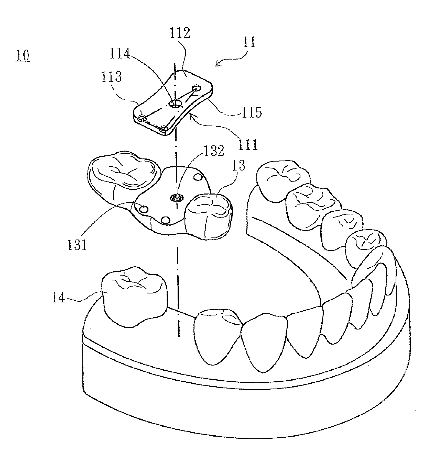
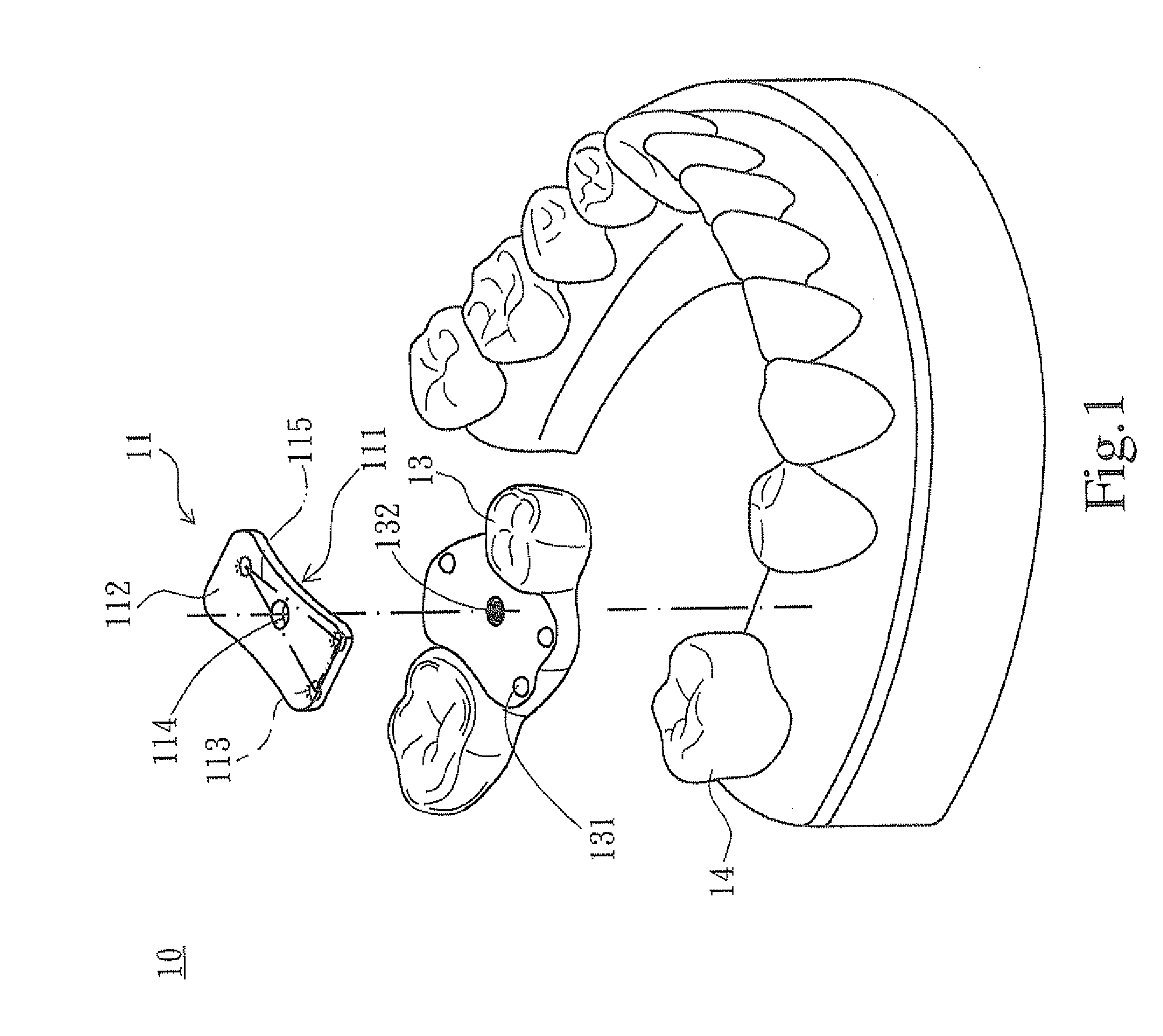
[0040]Referring to FIG. 1, a surgical template positioning device 10 according to one embodiment of the present invention is illustrated, wherein the surgical template positioning device 10 mainly comprises: a template 11, and a dental mold 13. The template 11 has a facing-down first surface 111 (i.e. a lower surface) and a facing-up second surface 11...


PUM


Abstract

A surgical template positioning device is provided, and has a template and a dental mold. The template has a first surface formed with at least three spherical recesses, a second surface, and a guiding hole. The dental mold has at least three spherical portions partially embedded in the at least three spherical recesses and an implanted hole having an axis the same as the guiding hole. The at least three spherical recesses have three spherical centers as being three vertices of a triangle, the axis passes through the triangle, and the at least three spherical portions have spherical centers corresponding with the three vertices of the triangle. A method of manufacturing the surgical positioning device is also provided.

Description

CROSS REFERENCE TO RELATED APPLICATIONS[0001]This application is a continuation-in-part application of U.S. patent application Ser. No. 13 / 904,044, filed on May 29, 2013, the disclosure of which is incorporated herein by reference.FIELD OF THE INVENTION[0002]The present invention relates to an artificial implant field, and more particularly to a method of manufacturing of a surgical template positioning device having spherical recesses and spherical portions.BACKGROUND OF THE INVENTION[0003]The tooth implant is a prosthetic tooth for substituting a whole tooth or a partial true tooth, and thus can solve the disadvantages that the traditional movable prosthetic tooth is not stably firmed or the bone matrix shrinks after many years. In the conventional implantation treatment, when the dentist performs an implant drilling surgery, the tooth implant is firstly designed based on a tooth computed tomography (CT) machine. Parameters during constructing a 3D model by scanning images can be ...

Claims


Application Information

Patent Timeline
IPC IPC(8): A61C1/08A61B6/14
CPCA61B6/14A61C1/084
Inventor CHENG, YING IUNGWANG, HSIAO CHINGHO, YI NUNG
Owner TAIWAN IMPLANT TECH
Why Eureka
Try Eureka