Apparatus and method for removing a shaft

a technology of shaft extractor and extractor, which is applied in the direction of metal-working apparatus, metal-working hand tools, metal-working apparatus, etc., can solve the problems of difficult removal of mandrels from unwind stands (or like machines), large manual labor, and large labor intensity, so as to reduce the time required, reduce labor intensity, and efficiently and effectively remove long, delicate shafts from objects

Inactive Publication Date: 2015-04-16
THE PROCTER & GAMBLE COMPANY
View PDF22 Cites 0 Cited by
  • Summary
  • Abstract
  • Description
  • Claims
  • Application Information

AI Technical Summary

Benefits of technology

[0006]The present invention addresses the need for an apparatus and method that efficiently and effectively removes long, delicate shafts from objects, reducing the time required to less than a half hour and minimizing manual effort. In one nonlimiting example of the present invention, an apparatus comprising a torquing device, threaded rod, support frame, retractable portion, tensional coupler and collar is provided. The torquing device is disposed on a first end of the threaded rod, and the threaded rod threads through a support frame and terminates at a second end that is in a rotatably free relationship with the retractable portion. The collar is connected to the retractable portion through the tensional coupler and is capable of grasping an engagement portion of the shaft.

Problems solved by technology

Yet, removal can prove challenging when shafts are tightly secured within or to their respective machines.
Moreover, due to the design of unwind stands, the mandrels are relatively light in weight and delicate.
The combination of these design elements and close tolerances makes removal of a mandrel from an unwind stand (or like machine) particularly difficult.
Indeed, known shaft and mandrel pullers fall short in ensuring the safe and efficient removal of mandrels on papermaking machines as they are not designed to account for their length and delicate nature.
Not only does this place individuals in a potentially unsafe situation, but the mandrel itself, which can be quite expensive, is at risk of being damaged or broken.

Method used


Image

  • Apparatus and method for removing a shaft
  • Apparatus and method for removing a shaft
  • Apparatus and method for removing a shaft

Examples


Embodiment Construction

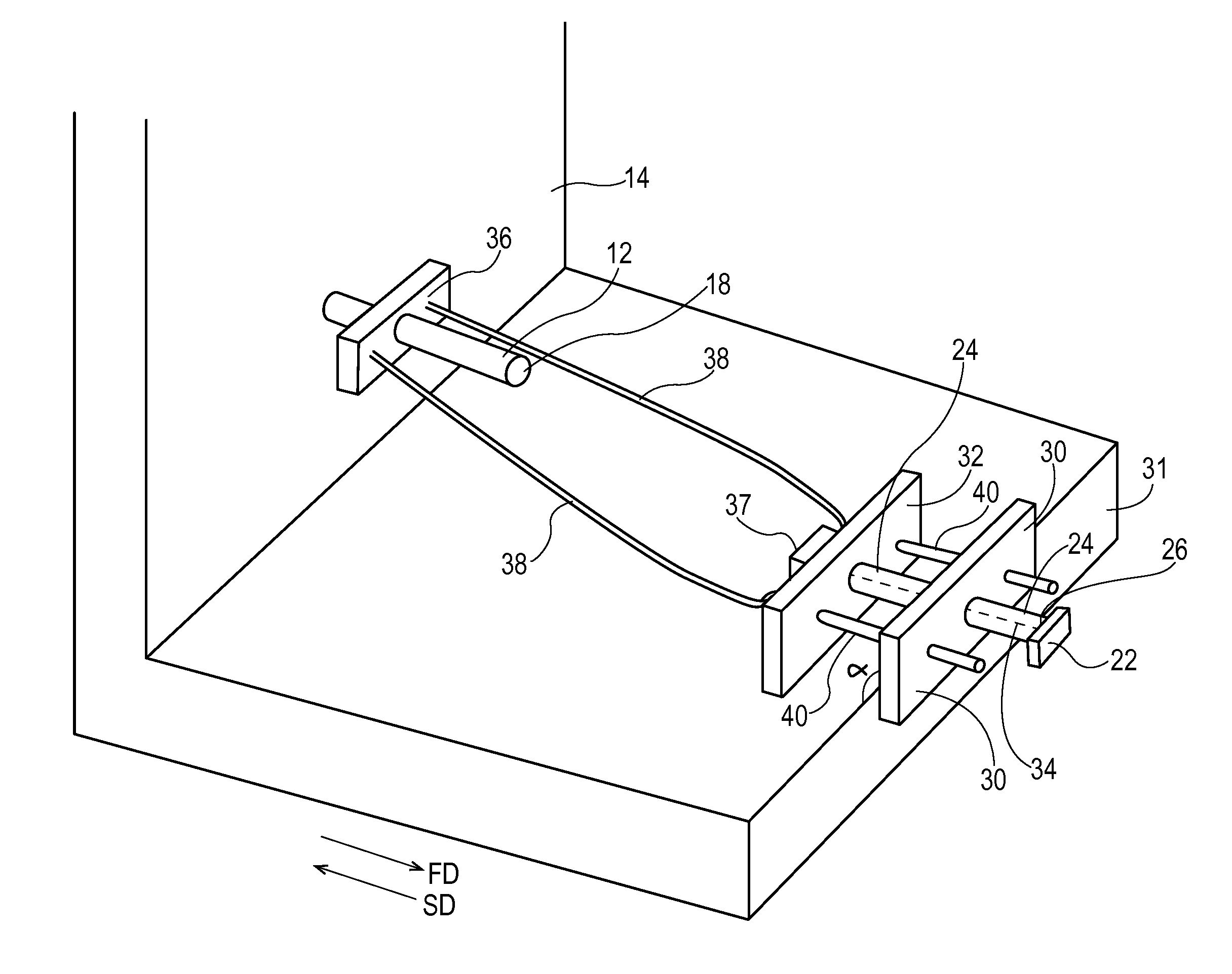
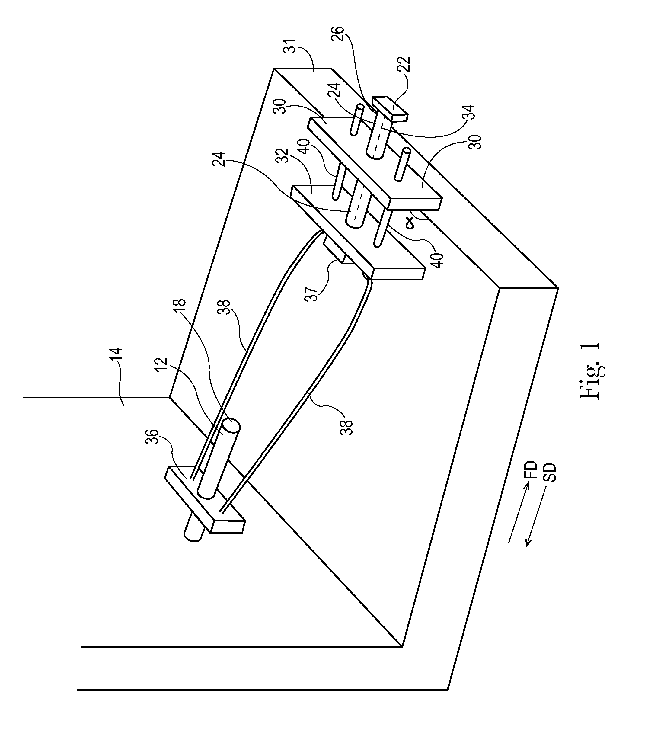
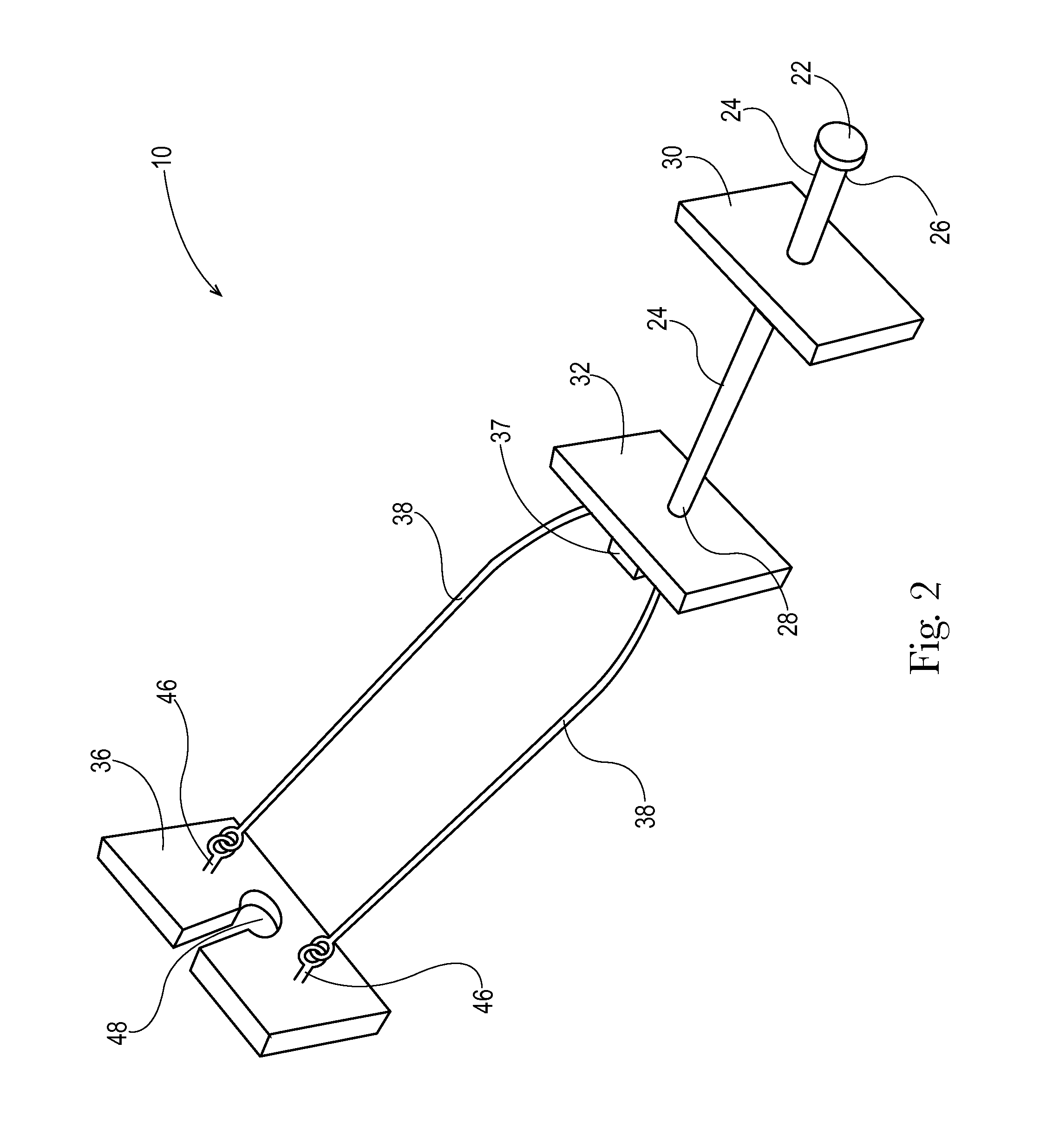
[0031]The present disclosure provides for equipment and methods for extracting a shaft from an object. Various nonlimiting embodiments of the present disclosure will now be described to provide an overall understanding of the principles of the function, design and use of the shaft extractor and methods disclosed herein. One or more examples of these nonlimiting embodiments are illustrated in the accompanying drawings. Those of ordinary skill in the art will understand that the apparatuses and methods described herein and illustrated in the accompanying drawings are nonlimiting example embodiments and that the scope of the various nonlimiting embodiments of the present disclosure are defined solely by the claims. The features illustrated or described in connection with one nonlimiting embodiment can be combined with the features of other nonlimiting embodiments. Such modifications and variations are intended to be included within the scope of the present disclosure.

DEFINITIONS

[0032]“...


PUM

PropertyMeasurementUnit
lengthaaaaaaaaaa
lengthaaaaaaaaaa
diameteraaaaaaaaaa

Abstract

An apparatus and method for extracting shafts is provided. The apparatus includes a torquing device, threaded rod, support frame, retractable portion, tensional coupler and collar. The torquing device is disposed on a first end of the threaded rod, and the threaded rod threads through a support frame and terminates at a second end that is in a rotatably free relationship with the retractable portion. The collar is connected to the retractable portion through the tensional coupler and is capable of grasping an engagement portion of the shaft. The method includes providing a shaft associated with an object, providing the apparatus, grasping the engagement portion of the shaft with the collar, positioning the support frame of the apparatus adjacent to a support wall and applying force while rotating the torquing device of the apparatus, resulting in the shaft being extracted.

Description

FIELD OF THE INVENTION[0001]The present invention relates to a shaft extractor and method for extracting a shaft, and more particularly a shaft extracting apparatus and method for extracting long, delicate shafts.BACKGROUND OF THE INVENTION[0002]Machines often require the attachment or placement of a shaft to serve as an arm, spindle, extension or other function. These shafts can be secured tightly, at times even pressure fitted, within the machine. Removal of shafts may be necessary for a variety of reasons such as cleaning, maintenance and design changes. Yet, removal can prove challenging when shafts are tightly secured within or to their respective machines.[0003]In the tissue towel industry, shafts in the form of mandrels are utilized at various stages of the papermaking process. For example, mandrels are attached to an unwind stand and serve as a location for the core of a roll of a convolutely wound roll of paper. The unwind stand drives the mandrel in a rotatable manner, and...

Claims


Application Information

Patent Timeline
Patent Type & Authority Applications(United States)
IPC IPC(8): B25B27/00
CPCB25B27/00B25B27/023B65H2601/324B65H2801/84B25B27/04Y10T29/49822Y10T29/53857Y10T29/53861Y10T29/53891Y10T29/53848B23P19/022B23P19/025
Inventor TREPANIER, RICHARD ALLEN
Owner THE PROCTER & GAMBLE COMPANY
Why Eureka
Try Eureka