
Filter system for filtering water or wastewater and a method of operating the filter system

Inactive Publication Date: 2007-09-13
RG DELAWARE
View PDF20 Cites 2 Cited by
  • Summary
  • Abstract
  • Description
  • Claims
  • Application Information

AI Technical Summary

Benefits of technology

[0004] Another object of a preferred embodiment of the present invention is to provide a method of operating an active filter system that does not require a washing fluid to be directed in a direction opposite to the flow of influent during filtration thus considerably simplifying operation and structure of the filter system.
[0005] A further object of a preferred embodiment of the present invention is to obviate the need to use filtered water to remove the coating of active materials from the plastic media particles.
[0006] Yet another object of a preferred embodiment of the present invention is to provide a method of operating an active filter system that does not require high volumes of washing fluid to expand the filter bed downwardly to remove the coating of active material from the plastic media particles.
[0007] Still another object of a preferred embodiment of the present invention is to provide a method of operating an active filter system that effectively and efficiently removes spent coating of active material from the plastic media particles.

Problems solved by technology

Overtime, the performance capacity of the active material is degraded through a combination of adsorption of dissolved solids and blinding by accumulation of solid material at the surface.
This method is very inefficient as it uses high volumes of treated water that is directed to waste rather than provided for service.

Method used


Image

  • Filter system for filtering water or wastewater and a method of operating the filter system
  • Filter system for filtering water or wastewater and a method of operating the filter system
  • Filter system for filtering water or wastewater and a method of operating the filter system

Examples


Embodiment Construction

[0016] The preferred forms of the invention will now be described with reference to FIGS. 1-4. The appended claims are not limited to the preferred forms and no term and / or phrase used herein is to be given a meaning other than its ordinary meaning unless it is expressly stated that the term and / or phrase shall have a special meaning. The term filter as used herein is to broadly interpreted to include a device in which at least a portion of the impurities in a liquid are removed including but not limited to a clarifier, a polishing filter and / or a contactor.

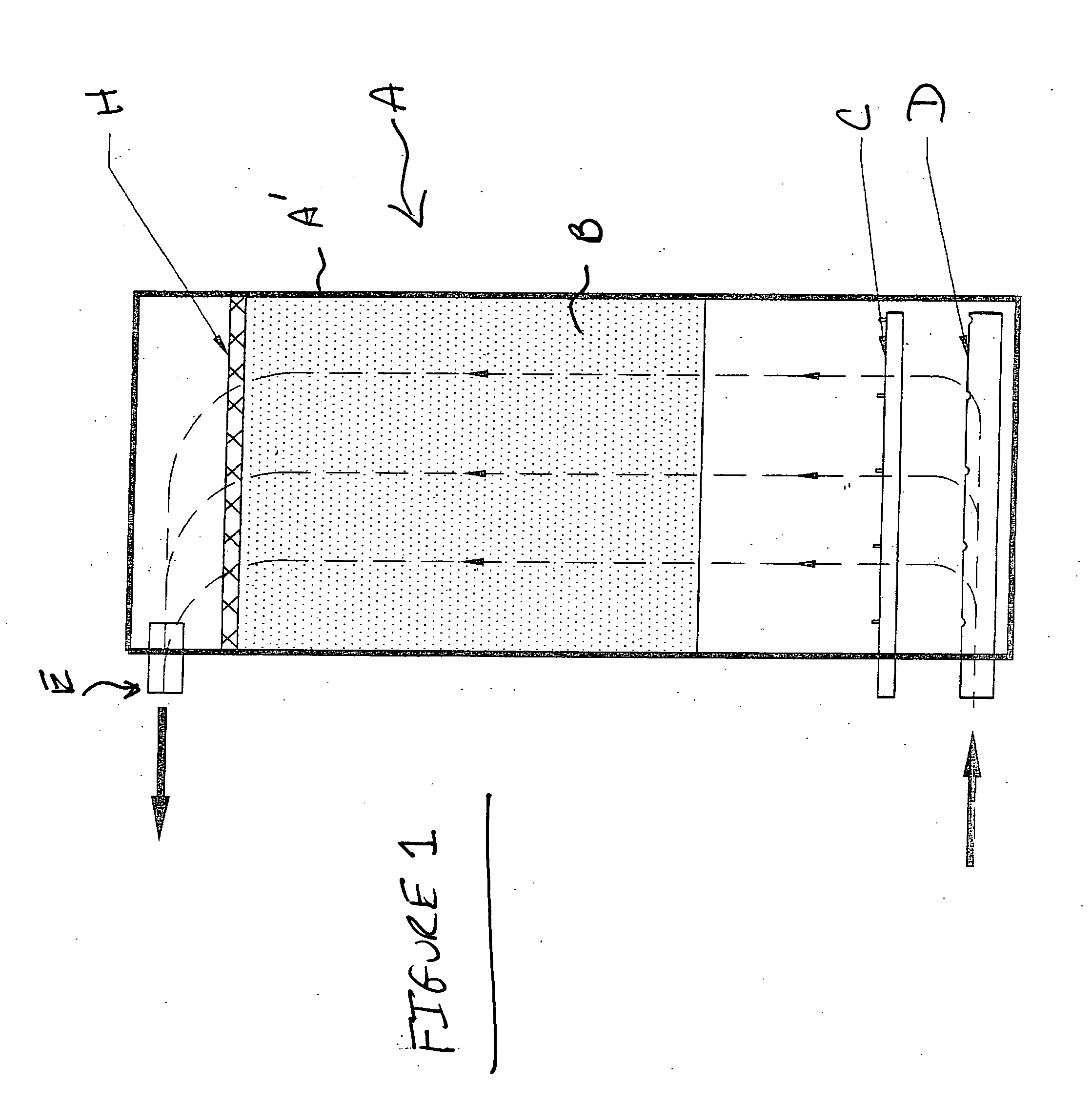
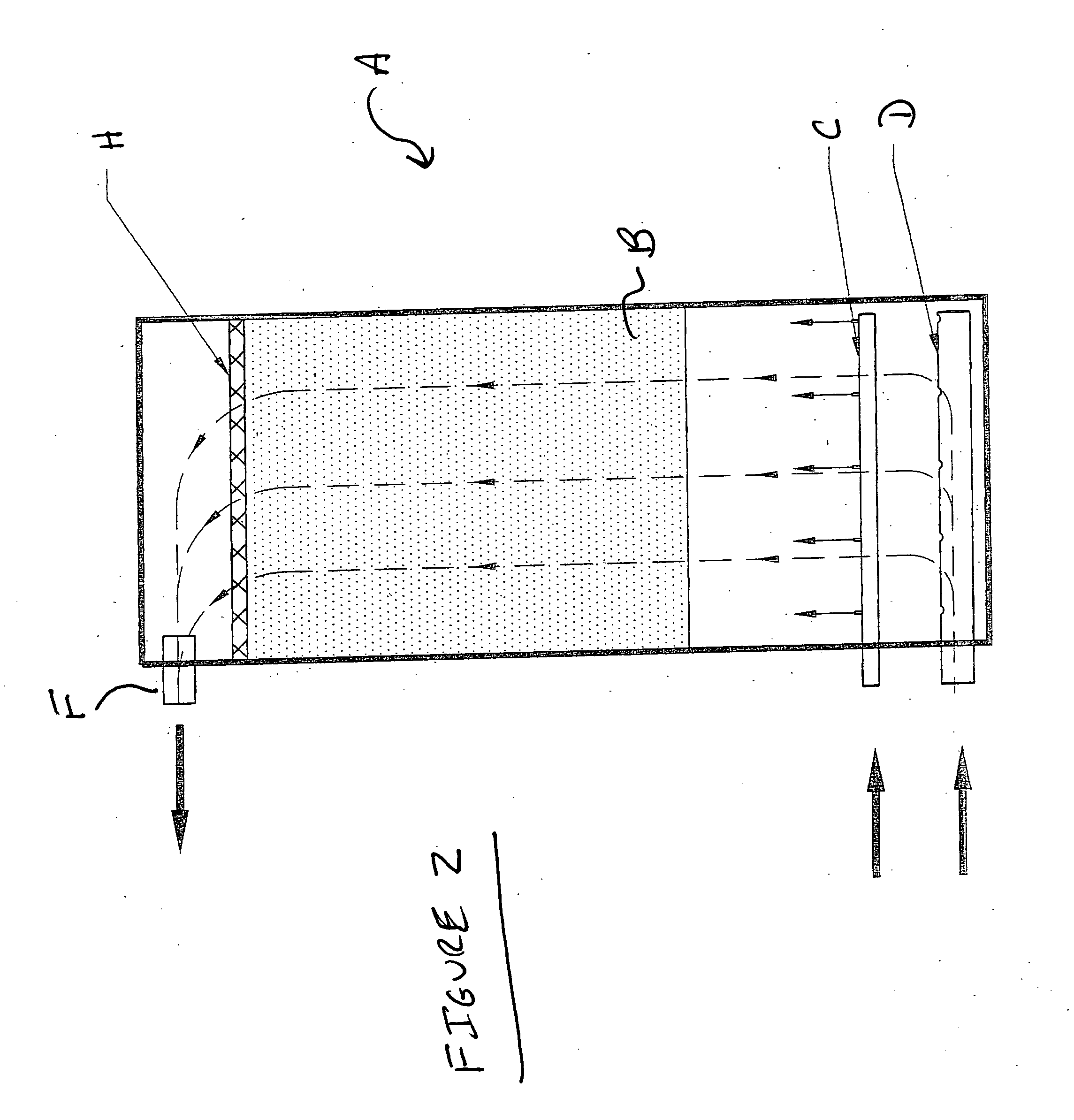
FIGS. 1-3

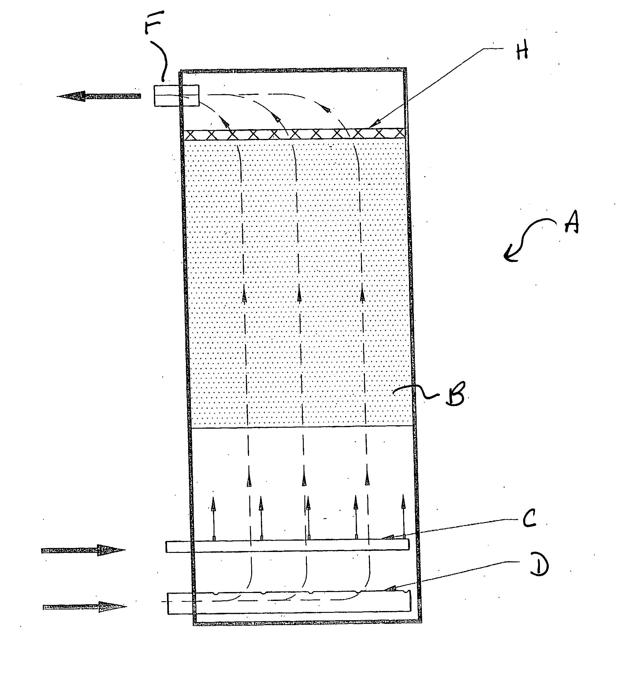
[0017] Referring to FIGS. 1 to 3, a portion of a filter system A is illustrated in one of many possible configurations. The filter system A includes a filter housing A′, a filter bed B, an air conduit C, an influent distribution manifold D, an effluent discharge port E, a waste discharge port F, a carbon slurry container G and a media retaining screen H.

[0018] The effluent discharge port E and waste discharge port F ar...


PUM

PropertyMeasurementUnit
Timeaaaaaaaaaa
Specific gravityaaaaaaaaaa
Velocityaaaaaaaaaa

Abstract

An active filter system having a filter bed formed from at least one layer of filter media and a method of operating the active filter system to filter water or wastewater. The filter media includes a plurality of plastic particles coated with an active material. Preferably, the active material is removed from the plastic particles by directing influent (i.e., untreated water) upwardly though the filter bed for a predetermined period of time. While the influent is directed upwardly through the filter bed, air is periodically directed upwardly through the filter bed so that the washing cycle includes a plurality of combined air and influent stages and a plurality of influent only stages. The coated plastic filter media particles have a specific gravity less than the specific gravity of the influent as well as the specific gravity of the combined air and influent washing fluid so that the coated plastic filter media remains buoyant during the washing cycle.

Description

FIELD OF THE INVENTION [0001] The present invention is directed to water and / or wastewater filter systems for filtering impurities from a liquid. More particularly, the present invention is directed to a filter system having active filtering particles and a method of operating the filter system. BACKGROUND OF THE INVENTION [0002] The Harberer process is a know method of producing and operating active filters to remove various organic and inorganic dissolved solids from water and wastewater. The Harberer process is disclosed in U.S. Pat. No. 4,208,281 the entire contents of which are hereby incorporated by reference. The filter bed includes buoyant plastic balls that are coated with an active material. Specifically, a liquid containing the active material is directed upwardly through the filter bed to cause the active material to be distributed on and adhere to the surfaces of the plastic balls at a predetermined flow rate. The active material is a carbon (sometimes referred to as po...

Claims


Application Information

Patent Timeline
IPC IPC(8): B01D29/46
CPCB01D24/165B01D24/4621C02F2303/16C02F1/283C02F1/288C02F1/281
Inventor MACKAY, DONALD JOHN
Owner RG DELAWARE
Learn More