Ionic liquid catalyst regeneration

Active Publication Date: 2019-12-19
UOP LLC
View PDF0 Cites 0 Cited by
  • Summary
  • Abstract
  • Description
  • Claims
  • Application Information

AI Technical Summary

Benefits of technology

[0007]It has been discovered that the hydrogen gas used to regenerate the spent ionic liquid catalyst be reduced from what is currently utilized. Conventional hydroprocessing processes recycle hydrogen gas to provide a large excess of hydrogen above the stoichiometric requirements, typic

Problems solved by technology

When too much conjunct polymer is present, the acid catalyst loses its effectiveness.
Sulfuric acid and hydrofluoric acid are hazardous and corrosive, and their use in i

Method used


Image

  • Ionic liquid catalyst regeneration
  • Ionic liquid catalyst regeneration

Examples


Example

Example 1: Ionic Liquid Catalyst Comprising Anhydrous Metal Halide

[0070]Various ionic liquid catalysts made of metal halides such as AlCl3, AlBr3, GaCl3, GaBr3, InCl3, and InBr3 could be used for the catalytic processes. N-butylpyridinium chloroaluminate (C5H5NC4H9Al2Cl7) ionic liquid catalyst is an example used in the present processes. The ionic liquid catalyst has the following composition:

[0071]Al 12.4 (wt. %)

[0072]Cl 56.5 (wt. %)

[0073]C 24.6 (wt. %)

[0074]H 3.2 (wt. %)

[0075]N 3.3 (wt. %)

Example

Example 2: Alkylation of C4 Olefin and Isobutane to Produce Alkylate Gasoline

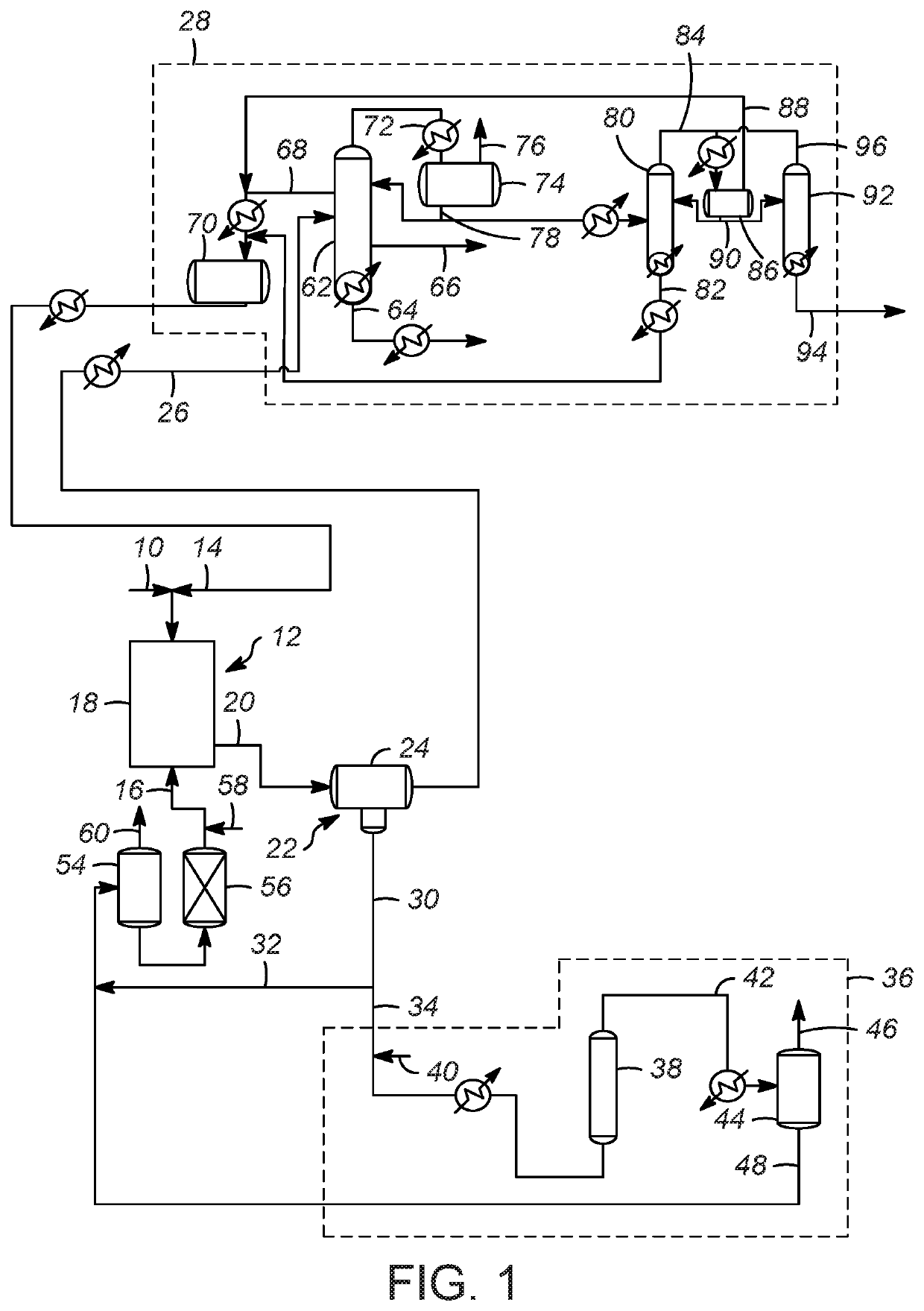
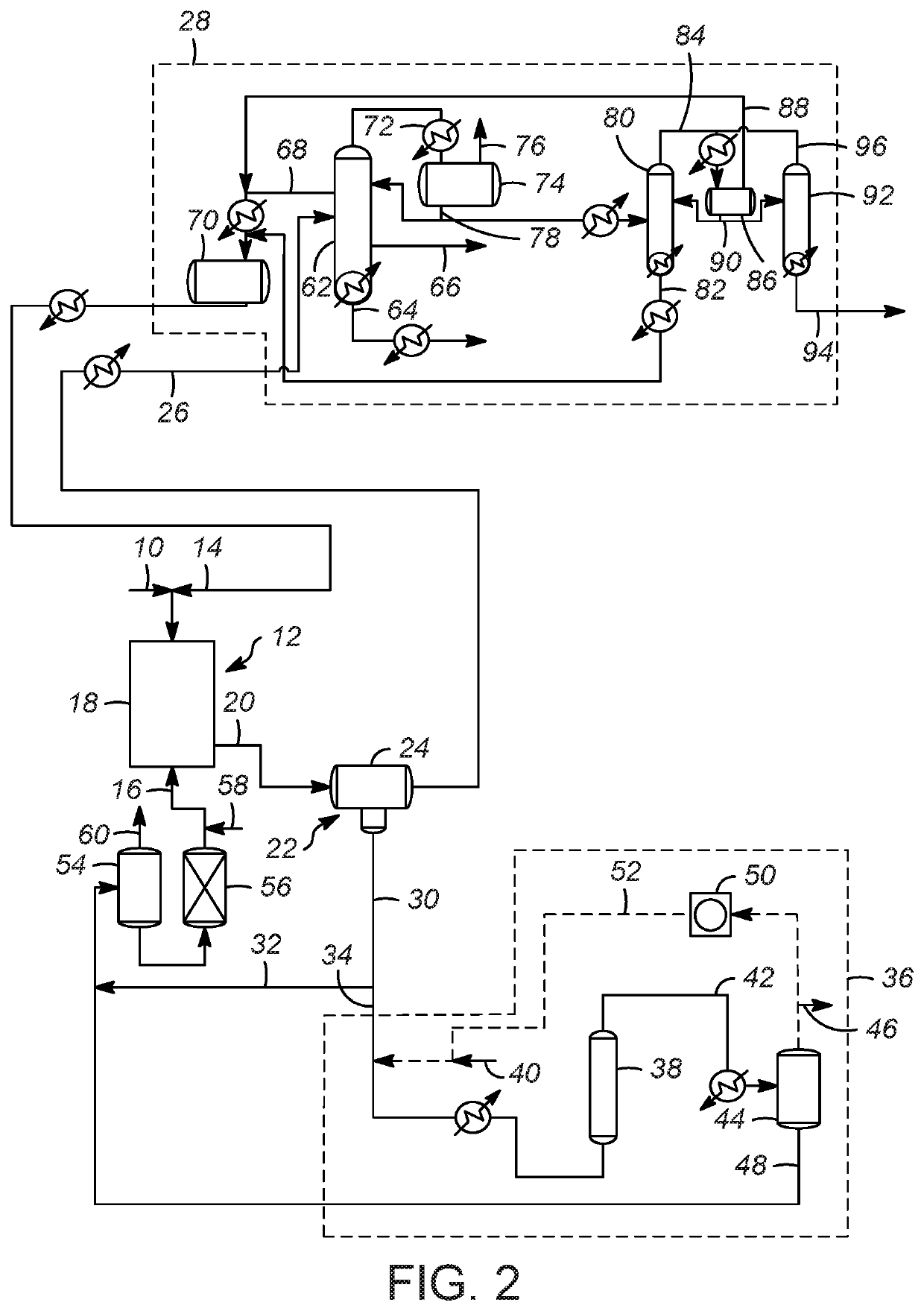
[0076]Evaluation of C4 olefins alkylation with isobutane was performed in a continuously stirred tank reactor using typical refinery mixed C4 olefin feed and isobutane. A 10:1 molar mixture of isobutane and olefin was fed to the reactor while vigorously stirring. An ionic liquid catalyst was fed to the reactor via a second inlet port targeting to occupy 5-6 vol % in the reactor. A small amount of n-butyl chloride was added to produce anhydrous HCl gas. The average residence time (combined volume of feeds and catalyst) was about 5 minutes. The outlet pressure was maintained at approximately 1380 kPa (200 psig) and the reactor temperature was maintained at 35° C. (95° F.) using external cooling.

[0077]The reactor effluent was separated with a gravity separator and then through a coalescer into a hydrocarbon phase and an ionic liquid catalyst phase. The hydrocarbon stream was further separated into multiple str...

Example

Example 3: Regeneration of Ionic Liquid Catalyst with Hydrogen Gas

[0078]The spent ionic liquid catalyst was sent to an on-line regeneration unit operated at 176.7° C. (350° F.) and 5,516 kPa (800 psig) and 0.15 LHSV without any solid regeneration catalyst. The hydrogen flow was varied in the range of 520 to 2,200 SCF H2 / BBL ionic liquid to examine the performance of the regeneration process as a function of hydrogen gas flow. To facilitate intimate contact between the spent ionic liquid catalyst with hydrogen gas, a bubble column reactor described in U.S. Pat. No. 9,802,186 was used. The hydrogenation reactor effluent was separated into gas and liquid stream. The conjunct polymer in the ionic liquid catalyst was converted to light hydrocarbon materials and HCl. The liquid stream containing liquid hydrocarbon and regenerated ionic liquid catalyst was sent to a catalyst surge drum and then to the alkylation reactor. The hydrogenation reactor offgas from the gas-liquid separation unit ...


PUM

PropertyMeasurementUnit
Volumeaaaaaaaaaa
Volumeaaaaaaaaaa
Volumeaaaaaaaaaa

Abstract

Processes for regenerating ionic liquid catalyst in which reaction vessel is operated under conditions sufficient to perform, in the presence of an ionic liquid catalyst, a hydrocarbon conversion reaction and provide a reaction effluent. The reaction effluent is separated into a hydrocarbon phase and a spent ionic liquid catalyst, wherein the spent ionic liquid catalyst includes conjunct polymer. The spent ionic liquid catalyst is contacted with hydrogen in a regeneration zone at conditions sufficient to reduce an amount of conjunct polymer in the spent ionic liquid catalyst to provide a regenerated effluent. The regenerated effluent is separated into a liquid phase comprising regenerated ionic liquid catalyst and a vapor phase comprising hydrogen and hydrogen chloride. The hydrocarbon phase is separated into a plurality of liquid hydrocarbon streams. The vapor phase is isolated from the liquid hydrocarbon streams. Alkylation processes are also disclosed.

Description

FIELD OF THE INVENTION[0001]This invention relates generally to ionic liquid regeneration processes, and more specifically to ionic liquid regeneration processes that use a lower amount of hydrogen, and even more particularly to alkylation processes that utilize the ionic liquid catalyst and regenerate the ionic liquid catalyst with hydrogen.BACKGROUND OF THE INVENTION[0002]Commercially, the alkylation of isoparaffins has been catalyzed by acids such as sulfuric acid and hydrofluoric acid. Conjunct polymer (acid soluble oils, (ASO) also known as red oil) forms as a byproduct of the alkylation reaction, as well as other hydrocarbon reactions. When too much conjunct polymer is present, the acid catalyst loses its effectiveness. The acid must be replaced with stronger acid, or the conjunct polymer must be removed in order to reactivate the catalyst. With sulfuric acid as the catalyst, the ASO is burned, and with hydrofluoric acid, the hydrofluoric acid is distilled away from the ASO. S...

Claims


Application Information

Patent Timeline
IPC IPC(8): B01J38/10B01J31/02B01J31/40C07C2/58
CPCB01J31/0284C07C2/58B01J31/4015B01J31/0298C07C2531/02B01J38/10C07C2/60B01J31/0277B01J2531/31B01J2231/323B01J2531/32B01J2531/33Y02P20/584C07C9/16
Inventor CARTER, ELIZABETHSPINNER, JOEL B.
Owner UOP LLC
Why Eureka
Try Eureka