Powder coating system

Active Publication Date: 2015-04-16
DENSO CORP
View PDF14 Cites 5 Cited by
  • Summary
  • Abstract
  • Description
  • Claims
  • Application Information

AI Technical Summary

Benefits of technology

The present invention provides a powder coating system that can increase the rate at which powder coating is applied to a material and improve the final utilization rate of the powder coating on metal cylindrical members that do not require coating of the internal circumferential surface. This helps to improve the overall efficiency of the powder coating process.

Problems solved by technology

Further, since the coating booth was large in size, the required capacity and size of the powder collector for collecting and recovering the powder coating after coating also became large.
It was difficult to reduce the size and streamline the powder coating facilities.
The remaining powder coating is recovered for reuse, but after several times of use, the powder coating degrades and has to be replaced.

Method used


Image

  • Powder coating system
  • Powder coating system
  • Powder coating system

Examples


Embodiment Construction

[0023]Below, referring to the drawings, aspects of the present invention will be explained. In the embodiments, the same parts of the configurations are assigned the same reference numerals and explanations will be omitted. Further, in the present invention, as a coatable material, a metal cylindrical member will be explained as an example.

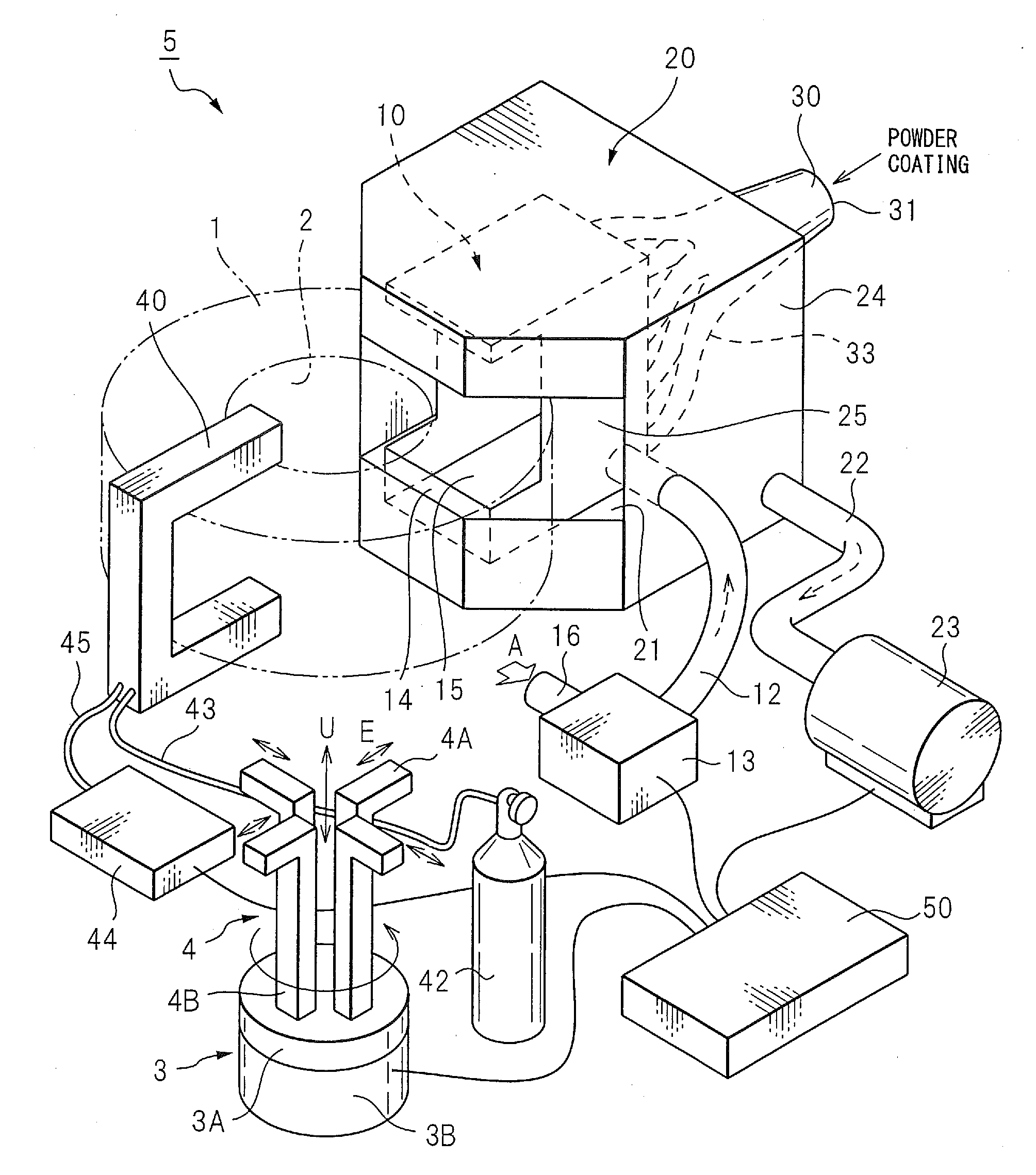
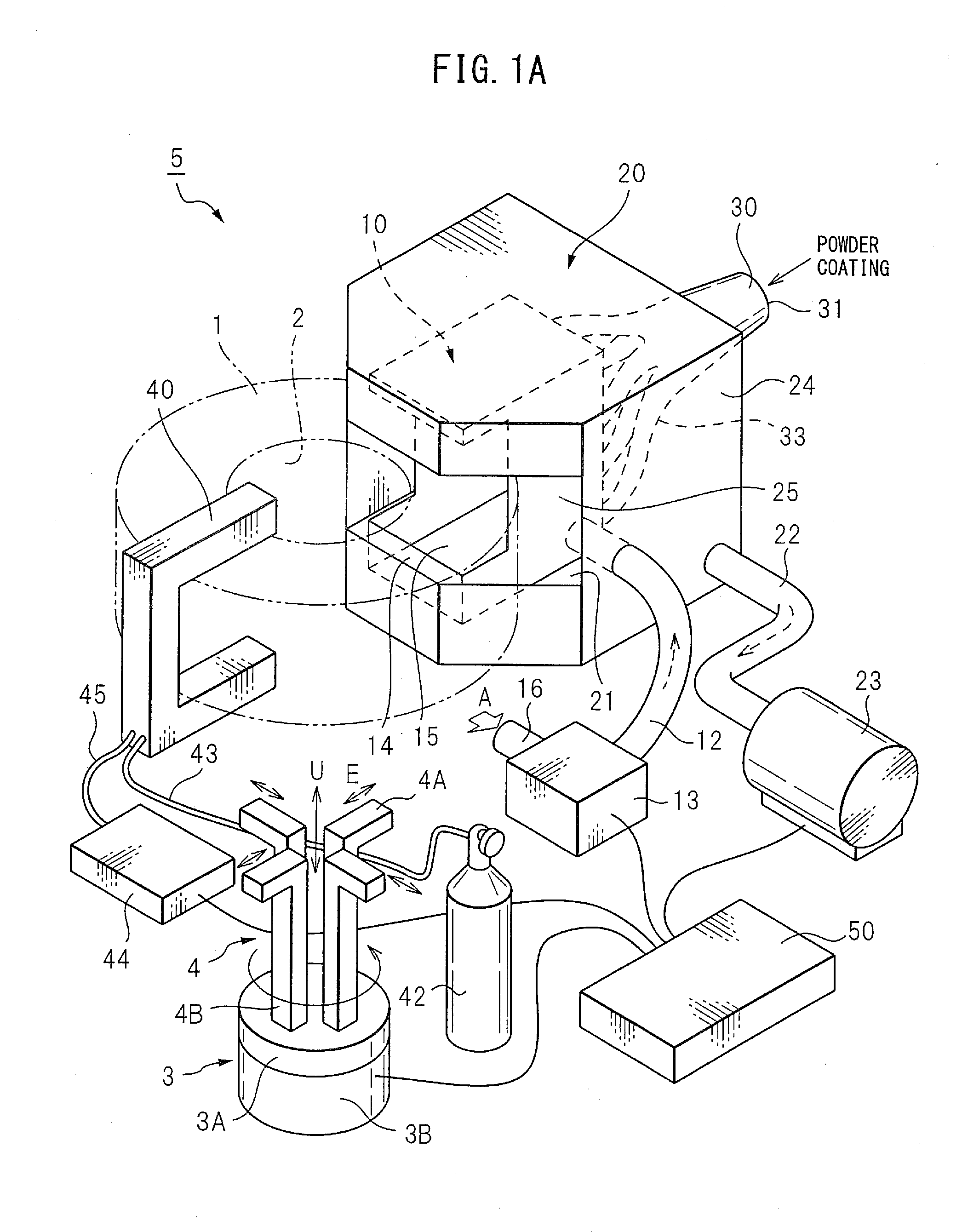
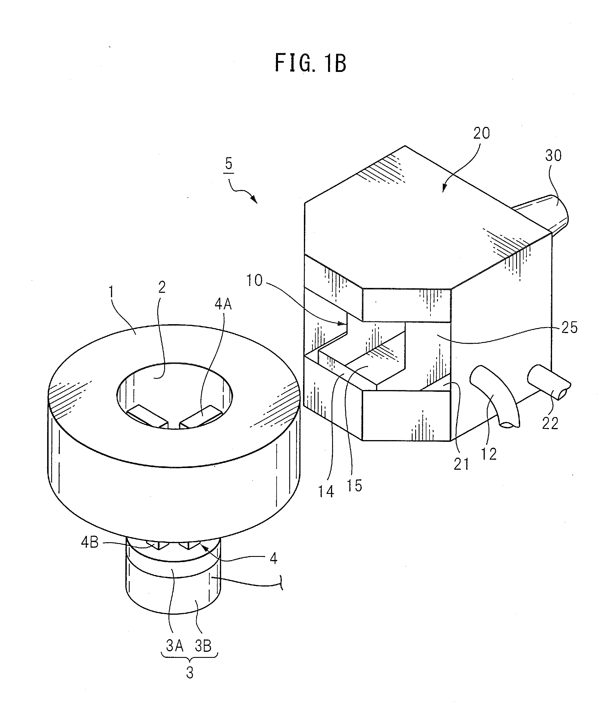
[0024]FIG. 1A is a perspective view which shows an example of the arrangement of the different members of a powder coating system 5 of a first aspect of the present invention. The powder coating system 5 of the first aspect can be provided with a rotating stage 3, first booth 10, second booth 20, powder coating introduction nozzle 30, plasma treatment device 40, and control device 50. The powder coating system 5 coats a metal cylindrical member 1 which is set at the position which is shown by the two-dot chain line by a powder coating.

[0025]The powder coating system 5 of the present invention is one which is used for coating a metal cylindrical me...


PUM

PropertyMeasurementUnit
Heightaaaaaaaaaa
Angular velocityaaaaaaaaaa
Flow rateaaaaaaaaaa

Abstract

A powder coating system which is provided with a rotating stage which makes a metal cylindrical member rotate while holding its internal circumferential surface, a first booth which covers part of the metal cylindrical member which is held by the rotating stage, and a second booth which holds the first booth. A powder coating introduction nozzle which is provided with a filling port of powder coating and a plurality of powder coating spray ports is provided so that a filling port is positioned at the outside of the second booth and so that the plurality of spray ports can be changed in position in the first booth to face surface parts of the metal cylindrical member. The sprayed powder coating is collected inside the second booth by a flow of air from a blow device and is removed by being sucked up by a powder collector.

Description

TECHNICAL FIELD[0001]The present invention relates to a powder coating system which uses a powder coating to coat a coatable material in a coating space.BACKGROUND ART[0002]As a coating method which forms a coating film of a thin uniform thickness on a surface part of a coatable material, the electrostatic powder coating method is known. As one example of such an electrostatic powder coating method, the method of coating a metal cylindrical member which uses a resin powder as a powder coating such as in PLT 1 is known. In electrostatic powder coating, first, the resin powder is charged by application of static electricity. Next, a coatable object charged with static electricity of the opposite polarity is coated with the charged resin powder to make the powder deposit on the surface of the coatable object. Finally, the coatable object is heated to make the resin powder which is deposited on the coatable object melt and form a coating film on the surface of the coatable object to the...

Claims


Application Information

Patent Timeline
IPC IPC(8): B05C5/02B05C9/10B05C13/00B05C19/04B05C19/06B05B12/16B05B14/00B05B14/10B05B14/30
CPCB05C5/027B05C19/04B05C19/06B05C5/0245B05C13/00B05C9/10B05B16/40B05B5/001B05B5/081B05B5/082B05B13/0228B05B5/12B05B7/1486Y10S118/07Y10S55/46B05B5/08B05B5/025
Inventor HASEBE, YUTAMIZUTORI, KAZUNORIKIDA, KOUJI
Owner DENSO CORP
Why Eureka
Try Eureka