Light source control device and light source control method

Active Publication Date: 2015-04-16
MITSUBISHI ELECTRIC CORP
View PDF3 Cites 13 Cited by
  • Summary
  • Abstract
  • Description
  • Claims
  • Application Information

AI Technical Summary

Benefits of technology

The patent describes a system that can detect and address short-circuit failures in multiple light sources. If a failure occurs, the system will identify which source is affected and quickly interrupt the supply of current to that source. This will allow the system to maintain the proper level of lighting. The overall effect of this system is to ensure consistent and reliable lighting levels even in the event of failure.

Problems solved by technology

In a structure with multiple parallel-connected LEDs, a short-circuit failure occurring even in one LED hinders flow of a current into a rest of LED of a higher resistance than the LED subjected to the short-circuit failure.
If the device continues to be used while one of multiple LEDs goes out due to its short-circuit failure, for example, a current is supplied intensively to the LED subjected to the short-circuit failure from the constant current circuit.
This becomes not only a cause for the aforementioned disabling of light-up of many LEDs but it is considered to also become a cause for a failure to occur in a rest of part of the device due to temperature increase resulting from heat generated by the LED subjected to the short-circuit failure.

Method used


Image

  • Light source control device and light source control method
  • Light source control device and light source control method
  • Light source control device and light source control method

Examples


first preferred embodiment

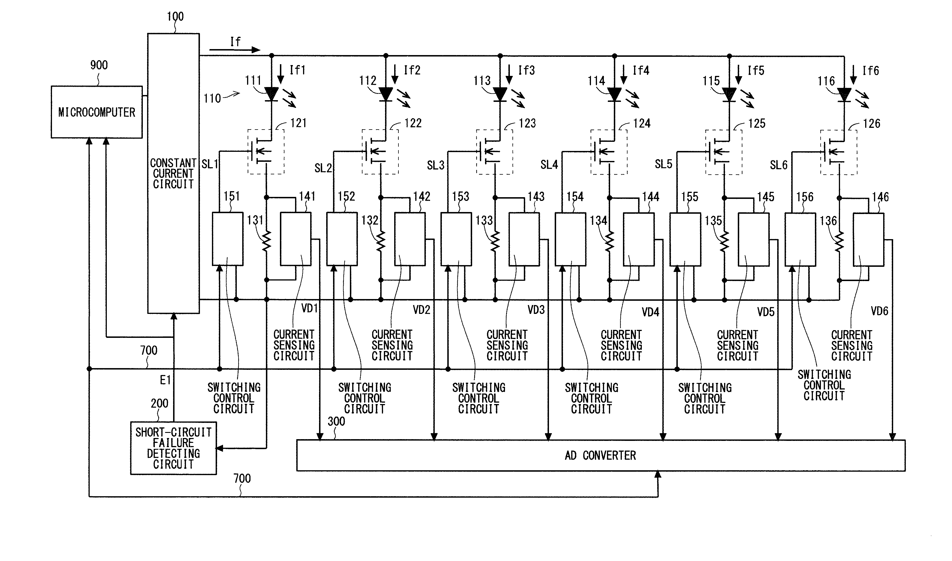
[0020]A light source control device of the present invention is to control multiple light sources connected in parallel. FIG. 1 is a block diagram showing an example of the structure of the light source control device according to a first preferred embodiment of the present invention. In the first preferred embodiment of the present intention described herein, the multiple light sources to be controlled are multiple (here, six) LEDs 111 to 116.

[0021]The LEDs 111 to 116 are elements to emit light in response to a current supplied to the LEDs 111 to 116. The LEDs 111 to 116 described herein are to emit light of the same color (one of red, green, and blue, for example). The LEDs 111 to 116 have the same specifications and the same characteristics in terms of the luminance of light to be emitted at the same current value, a forward drop voltage Vf and a rated current, for example. The LEDs 111 to 116 can be treated as one collection 110 of LED light sources.

[0022]The light source contro...

first modification

[0077]FIG. 9 is a flowchart showing the operation of a light source control device according to a first modification. The flowchart of FIG. 9 includes step S4a as an alternative to steps S4 and S5 of FIG. 6. The following mainly describes step S4a.

[0078]After receiving the detecting signal E1 at “H” from the short-circuit failure detecting circuit 200 indicating detection of the occurrence of a short-circuit failure, the constant current circuit 100 switches from supplying the driving current If to the LEDs 111 to 116 to supplying a failure detecting current to the LEDs 111 to 116 in step 54a. Specifically, if receiving the detecting signal E1 at “H” indicating detection of the occurrence of the short-circuit failure, the constant current circuit 100 does not stop supplying a current once but it supplies the failure detecting current to the LEDs 111 to 116 immediately.

[0079]This light source control device of the first modification supplies the failure detecting current independent...

second modification

[0080]The aforementioned light source control device can still provide an appropriate luminance even if a short-circuit failure occurs in any of the LEDs 111 to 116. However, a failure that might actually occur include not only a short-circuit failure but also an open-circuit failure. If any of the LEDs 111 to 116 goes out due to an open-circuit failure, a rated current or a current higher than the rated current flows into an LED not subjected to an open-circuit failure. This might cause a failure also in the LED not subjected to an open-circuit failure. As described below, in a second modification, even if an open-circuit failure occurs in any of the LEDs 111 to 116, an appropriate current can still be supplied to an LED not subjected to an open-circuit failure.

[0081]FIG. 10 is a flowchart showing the operation of a light source control device according to the second modification. The flowchart of FIG. 10 includes steps from S21 to S27 in addition to the steps in the flowchart of F...


PUM


Abstract

A microcomputer of a light source control device specifies an LED belonging to LEDs and subjected to a short-circuit failure based on a result of determination by a short-circuit failure detecting circuit and current amounts sensed by current sensing circuits respectively. The microcomputer makes corresponding one of switching elements interrupt supply of a current to the specified LED. The microcomputer makes a constant current circuit supply an LED not specified with a current not exceeding a current responsive to the number of such LEDs not specified.

Description

FIELD OF THE INVENTION[0001]The present invention relates to a light source control device to control multiple light sources connected in parallel and a method of controlling the light sources.BACKGROUND ART[0002]A collection of light sources such as multiple light-emitting diodes (hereinafter called “LEDs”) and lasers connected in parallel has been suggested as a light source for a projection type image display device. Connecting LEDs in parallel makes it possible to drive a large number of LEDs at a low voltage. Further, making multiple LEDs light up allows acquisition of high-luminance light and reduction in the power consumption of the entire device compared to a lamp light source of a conventional type.[0003]As an applicable device to control light-up of multiple LEDs, a device sets a driving current to be supplied from a constant current circuit to the LEDs connected in parallel by a controller such as a microcomputer. Luminance determined while the LED light up changes in res...

Claims


Application Information

Patent Timeline
IPC IPC(8): H05B33/08H05B44/00
CPCH05B33/089H05B33/0848H05B45/52H05B45/14
Inventor YONEOKA, LSAOASAMURA, YOSHINORIYAMAMOTO, ZENKOUINOUE, HARUHISA
Owner MITSUBISHI ELECTRIC CORP
Why Eureka
Try Eureka