Micro leakage detecting device of suspension device and method for detecting micro leakage

a technology of suspension device and leakage detection, which is applied in the direction of fluid pressure measurement, instruments, transportation and packaging, etc., can solve the problems of leakage, abnormal abnormal detection, and air compressed may leakage,

Inactive Publication Date: 2015-04-16
HYUNDAI MOBIS CO LTD
View PDF13 Cites 7 Cited by
  • Summary
  • Abstract
  • Description
  • Claims
  • Application Information

AI Technical Summary

Benefits of technology

[0019]According to exemplary embodiments of the present invention, it is possible to detect micro leakage that is not detected in a general fail-safe system to prevent a suspension device from being damaged and from being reduced its life span by determining micro leakage when the vehicle-height correcting type is repeated for the same vehicle-height correcting control more than a reference number.

Problems solved by technology

In the vehicle-height adjusting device, the compressed air may leak, and failure caused by the leakage may be detected and respond by the fail-safe system.
For example, when abnormal vehicle-height control is performed due to the leakage, when a time to perform the vehicle-height control is excessively taken, or when abnormality occurs in filling the air tank, the failure or abnormality is appropriately detected by the fail-safe system to restrict the corresponding system.
However, such failure corresponds to a case where leakage occurs and components are damaged to such an extent as not to control the suspension device.
When a pin hole is formed in the air spring or an air pressure line to cause the micro leakage, since the amount of leakage is not large, the micro leakage may not be detected by the fail-safe system.
Accordingly, when the micro leakage occurs, the vehicle-height correcting and the filling of the air tank are unnecessarily continued, and operating times of the compressor and the solenoid valve block are increased.
Thus, the components may be damaged and life spans thereof may be reduced.

Method used


Image

  • Micro leakage detecting device of suspension device and method for detecting micro leakage
  • Micro leakage detecting device of suspension device and method for detecting micro leakage
  • Micro leakage detecting device of suspension device and method for detecting micro leakage

Examples


Embodiment Construction

[0026]Hereinafter, exemplary embodiments of the present invention will be described in detail with reference to the accompanying drawings. It should be noted that throughout the accompanying drawings, the same components are assigned the same reference numerals even in different drawings. The exemplary embodiments of the present invention will now be described, but the technical sprit of the present invention is not limited or restricted thereto. Therefore, it should be appreciated that those skilled in the art can variously change and modify these embodiments.

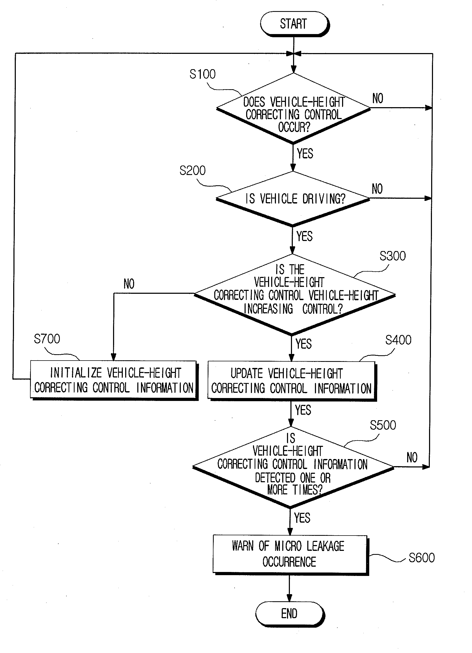
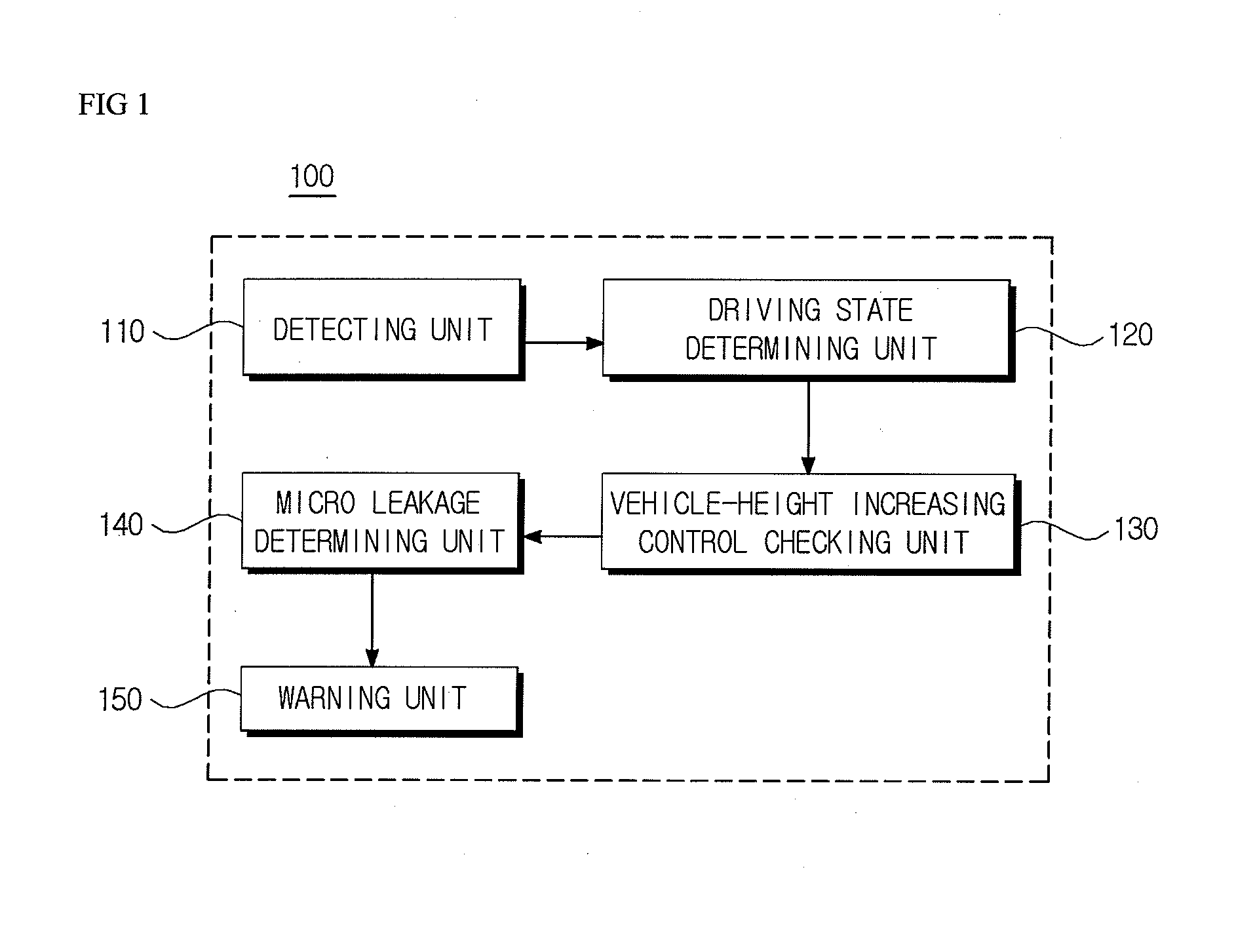
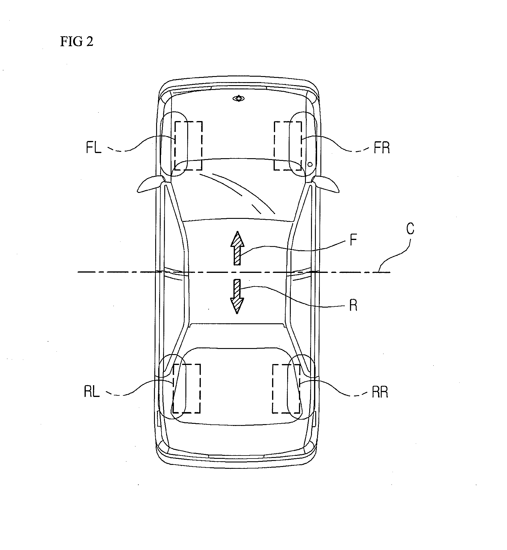
[0027]FIG. 1 is a diagram illustrating a micro leakage detecting device of a suspension device according to an exemplary embodiment of the present invention, FIGS. 2 and 3 are diagrams illustrating vehicle-height correcting control regions, and FIG. 4 is a flowchart illustrating a method for detecting micro leakage of a suspension device according to another exemplary embodiment of the present invention.

[0028]Referring to FIGS...


PUM


Abstract

A micro leakage detecting device of a suspension device includes a detecting unit, a driving state determining unit that checks whether or not a vehicle is driving when it is checked in the detecting unit that the vehicle-height correcting control occurs, a vehicle-height increasing control checking unit that checks whether or not the vehicle-height correcting control is control for increasing a vehicle height when it is checked in the driving state determining unit that the vehicle is driving, a micro leakage determining unit that updates vehicle-height correcting control information according to a vehicle-height correcting type when it is checked in the vehicle-height increasing control checking unit that the the vehicle-height correcting control is the control for increasing the vehicle height, and determines whether or not micro leakage occurs when the vehicle-height correcting control information is detected one or more times, and a warning unit that warns a driver.

Description

CROSS-REFERENCE TO RELATED APPLICATIONS[0001]This application claims priority to and the benefit of Korean Patent Application No. 10-2013-0120664 filed in the Korean Intellectual Property Office on Oct. 10, 2013, the entire contents of which are incorporated herein by reference.TECHNICAL FIELD[0002]The present invention relates to a micro leakage detecting device, and more particularly, to a micro leakage detecting device of a suspension device that adjusts a height of a vehicle by using air pressure.BACKGROUND ART[0003]A suspension device that has been currently used in a vehicle may have both a vehicle-height control function and a damping function. The vehicle-height control is used to adjust a vehicle height by using hydraulic pressure or air pressure. The vehicle height is decreased to reduce air resistance and improve handling performance during high-speed driving in a general paved road, whereas the vehicle height is increased to improve driving performance in a rough road.[0...

Claims


Application Information

Patent Timeline
Patent Type & Authority Applications(United States)
IPC IPC(8): B60Q9/00
CPCB60Q9/00B60G17/0185B60G2202/152B60G2400/204B60G2400/252B60G2500/02B60G2500/30B60G2600/044G01L19/0672G01L19/12G01M17/04B60G17/015B60G17/018
Inventor KIM, YOUNG IL
Owner HYUNDAI MOBIS CO LTD
Why Eureka
Try Eureka