
Subsea umbilical system with cable breakout

a technology of umbilical system and cable, which is applied in the direction of sealing/packing, coupling device connection, and well accessories, etc., can solve the problems negative affecting the performance of systems, and affecting the performance of medium voltage cables. , to achieve the effect of reducing the effectiveness of mechanical properties, reducing the life span of cables, and affecting system performan

Active Publication Date: 2015-07-28
AKER SOLUTIONS AS
View PDF12 Cites 6 Cited by
  • Summary
  • Abstract
  • Description
  • Claims
  • Application Information

AI Technical Summary

Benefits of technology

The patent text describes the problem of heat trapping in certain parts of an umbilical system, which can negatively affect its performance. This can result in decreased efficiency and damage to the system. The solution proposed is to break certain cables out of the system, which can allow them to operate at higher currents without overheating. This will improve the performance of the overall system without affecting its rigidity or load bearing capacity.

Problems solved by technology

It has been found that elements of certain umbilical systems can trap an undesirable amount heat within the system and that such heat trapping elements can negatively affect the performance of the system.
For example, in some situations, medium voltage cables are unable to reach a desired amperage capacity within an umbilical due to heat trapping characteristics of elements such as a bend stiffener, I-tube, J-tube, and / or potting barrel of the umbilical system.
That is, if such power cables are operated within these heat trapping elements at too high of a voltage, heat generated by the cable may build up to a level that can damage the umbilical or other elements of the umbilical system by decreasing the effectiveness of their mechanical properties, which can, in effect, reduce their life span.
Certain embodiments of the present description can avoid such undesirable heat trapping characteristics by breaking one or more cables out of the umbilical, such as power cables, and not allow excessive heat build-up within the umbilical due to heat trapping elements.

Method used


Image

  • Subsea umbilical system with cable breakout
  • Subsea umbilical system with cable breakout
  • Subsea umbilical system with cable breakout

Examples


first embodiment

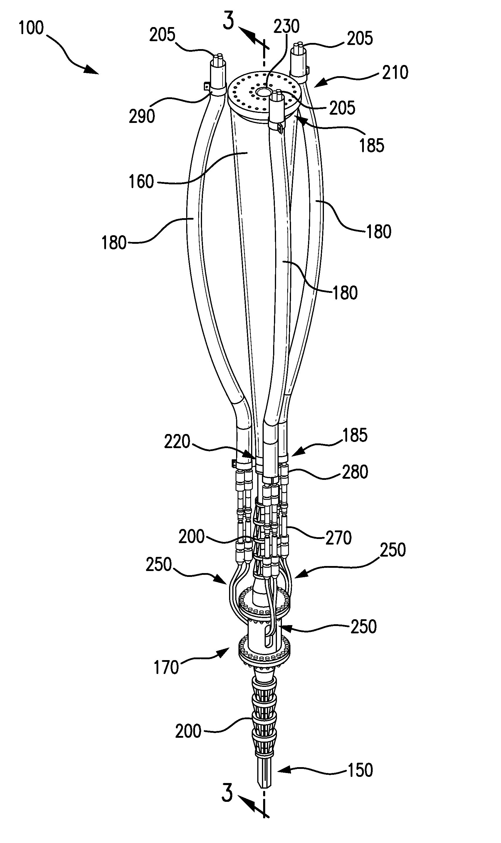
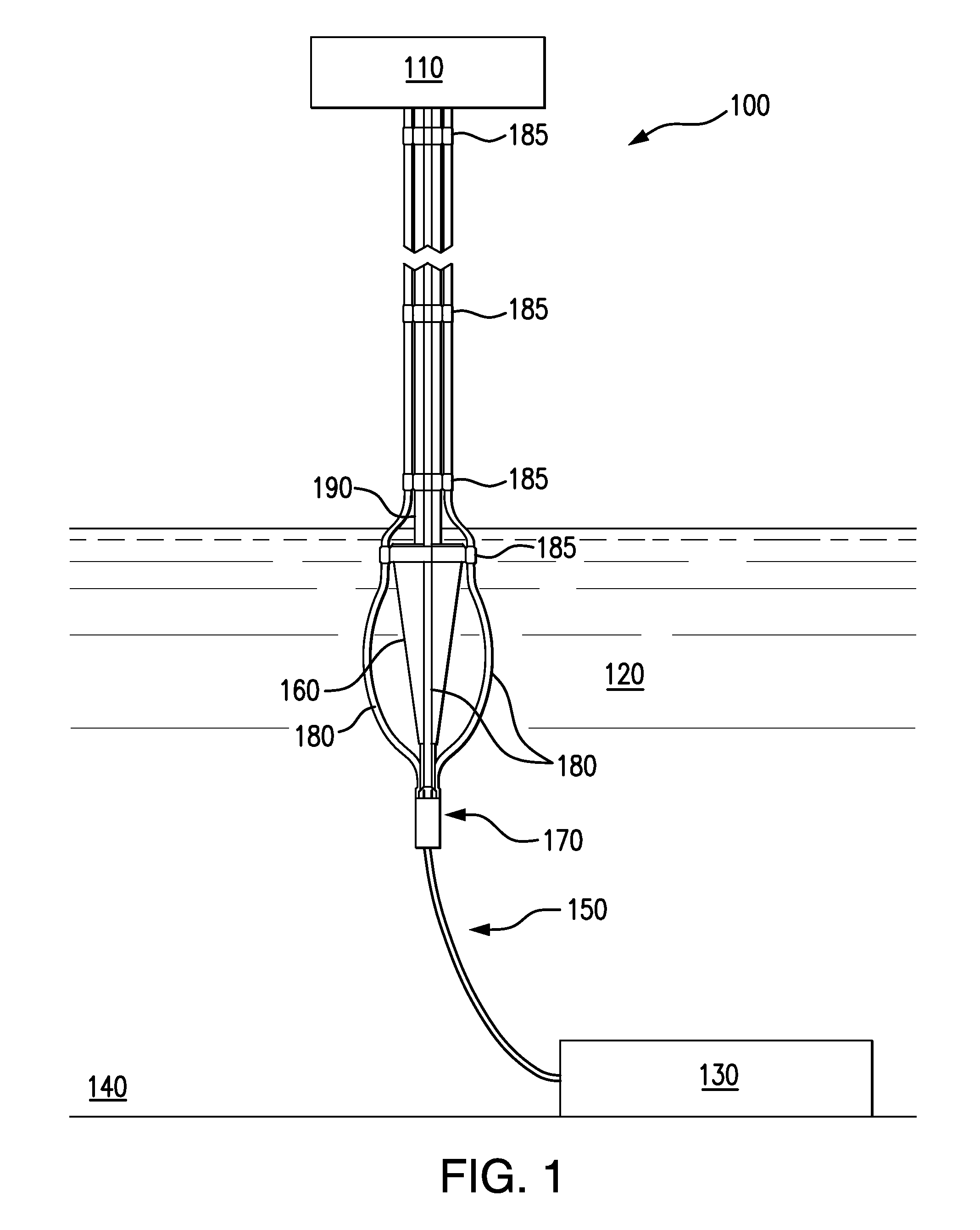
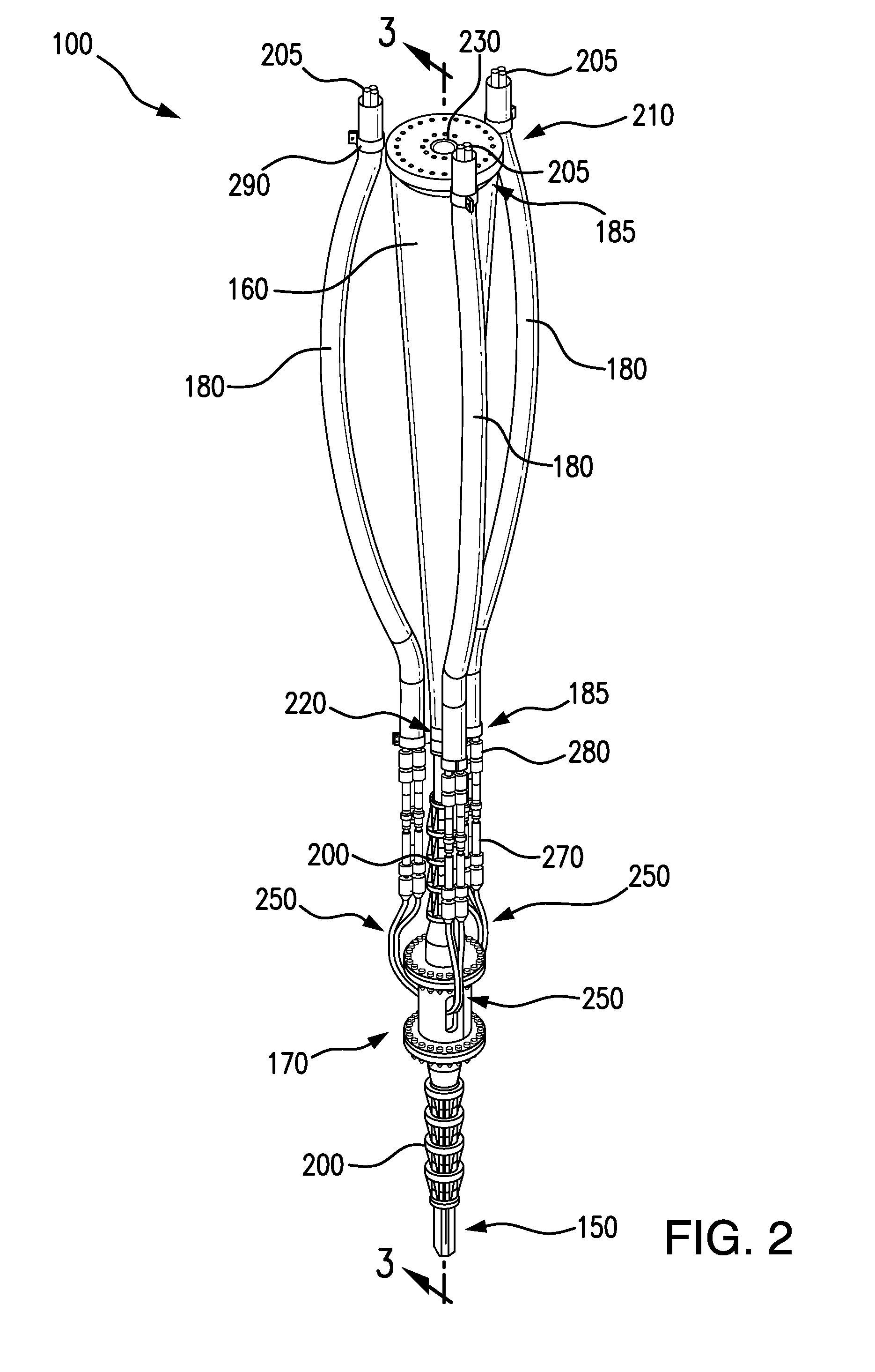
[0022]FIGS. 1-3 illustrates various views of a subsea umbilical system 100. In particular, FIG. 1 illustrates a diagram view of system 100 attached to a topside structure 110 above water line 120 and further attached to equipment 130 on seabed 140. FIG. 2 illustrates a front perspective view of system 100, and FIG. 3 illustrates a cross-sectional view of system 100 along line 3-3 of FIG. 2.

[0023]System 100, as well as other systems described herein, can be configured for use with deep-water subsea projects or other suitable subsea projects. In some embodiments, system 100 can be configured to connect at a first end to a topside structure 110, such as a floating platform and / or floating production facility. In some embodiments, topside structure 110 can be in the form of a ship. It is appreciated that in some embodiments, system 100 can be configured to connect at a first end to a non-floating structure, such as a structure supported entirely or partially by seabed 140. A second end ...

second embodiment

[0041]FIG. 8 illustrates a subsea umbilical system 470. System 470, like system 100 described in FIG. 1, can, for example, be configured for use with deep-water subsea projects or other suitable subsea projects. System 470 can include substantially similar elements as system 100, such as umbilical 150, bend stiffener 160, electrical flying leads 205, cluster conduits 180, cluster mounts 185, and bend restrictors 200. System 470 can additionally include a modified breakout box 480 that allows for the tensile load of the umbilical to be carried by the shell of the breakout box 480.

[0042]FIG. 9 illustrates an interior view of a portion of system 470, with a portion of breakout box 480 removed for clarity. As shown in FIG. 9, similar to breakout box 170, breakout box 480 is substantially hollow and includes multiple breakout openings 560 for permitting breakout cables 500 to exit breakout box 480. Breakout openings 560 can be provided near the top end of breakout box 480 or at another s...


PUM


Abstract

A subsea umbilical system can be provided for connecting a topside structure at a proximal end of the system to subsea equipment at a distal end of the system. The system can include an umbilical configured to allow one or more cables for powering or communicating with subsea equipment to be passed through at least a portion of the umbilical. The system can further include reinforcing elements radially surrounding a portion of the umbilical. The system can further include a breakout box disposed along the umbilical and configured to be positioned between the reinforcing element and the subsea equipment. The breakout box can include a breakout opening configured to allow one or more breakout cables to exit the umbilical and run along the outside of the reinforcing elements to the topside structure. Related methods of making and using such systems are also described.

Description

BACKGROUND[0001]1. Field[0002]The present invention relates generally to subsea development projects, and more particularly to improved subsea umbilical systems with one or more cable breakouts.[0003]2. Background[0004]Deep-water subsea projects can refer to offshore projects located in water depths greater than around 600 feet. Such projects can be used, for example, to develop and maintain oil and gas reservoirs. Subsea well equipment used for such projects can be located on the seabed and operatively connected to a topside surface structure, such as a ship or other floating platform. In such projects, one or more umbilicals are often used to convey fluids, power, and / or send electrical and other communication signals between the surface structure and the subsea well equipment. There is a continuous need for improved subsea umbilical systems for deep-water subsea projects as well as other subsea projects.BRIEF SUMMARY[0005]It has been found that elements of certain umbilical syste...

Claims


Application Information

Patent Timeline
Patent Type & Authority Patents(United States)
IPC IPC(8): E21B43/013
CPCE21B43/013E21B17/017H01R13/523E21B17/01E21B33/0355E21B43/12
Inventor WHIDDON, JOHNLITTLE, HEITH
Owner AKER SOLUTIONS AS
Learn More