
Reverse energy recovery circuit

a reverse energy and circuit technology, applied in the direction of electric variable regulation, process and machine control, instruments, etc., can solve the problems of affecting the power conversion, deteriorating the performance of peripheral elements (such as power elements, capacitors, etc., and preventing the reverse energy from damaging the electronic elements, shortening the life of the electronic elements

Active Publication Date: 2012-03-20
SPI ELECTRONICS
View PDF6 Cites 6 Cited by
  • Summary
  • Abstract
  • Description
  • Claims
  • Application Information

AI Technical Summary

Benefits of technology

[0004]In view of the deficiency of the aforesaid conventional technique, the primary object of the present invention is to provide a recovery circuit to suppress the reverse energy of the transformer and recover the reverse energy for reusing to prevent the reverse energy from damaging the electronic elements or shortening their life span.
[0006]The aforesaid charge and discharge paths can store and reuse the reverse energy stored in the transformer. The circuit structure is simpler and can be made at a lower cost without occupying too much space.

Problems solved by technology

Power conversion is affected by many factors, such as loss of elements and loss caused by leakage or mutual offset when energy is transformed to magnetic force during power conversion.
The reverse surge constantly applies to the elements connected to the transformer, as a result the performance of the peripheral elements (such as power elements, capacitors and the like) deteriorates after a period of time, even the life span of the elements could suffer.
Moreover, if the reverse surge energy is not properly guided, power conversion efficiency drops.
Even if the reverse surge energy has been properly guided, it still exists in the loss, hence total conversion efficiency of the circuit does not improve significantly.
It can suppress the surge and recover the energy, but still has a drawback, namely requires additional second transformer and second switch.
Not only its cost is higher, more space has to be allocated and occupied in the limited interior space of the power circuit casing.
Moreover, although the reverse surge energy is recovered to supply to the load, it has to go through transformation via the second transformer, and loss occurs by one more time of energy transformation to the secondary side.
The additional cost outweighs the generated benefit.

Method used


Image

  • Reverse energy recovery circuit
  • Reverse energy recovery circuit
  • Reverse energy recovery circuit

Examples


Embodiment Construction

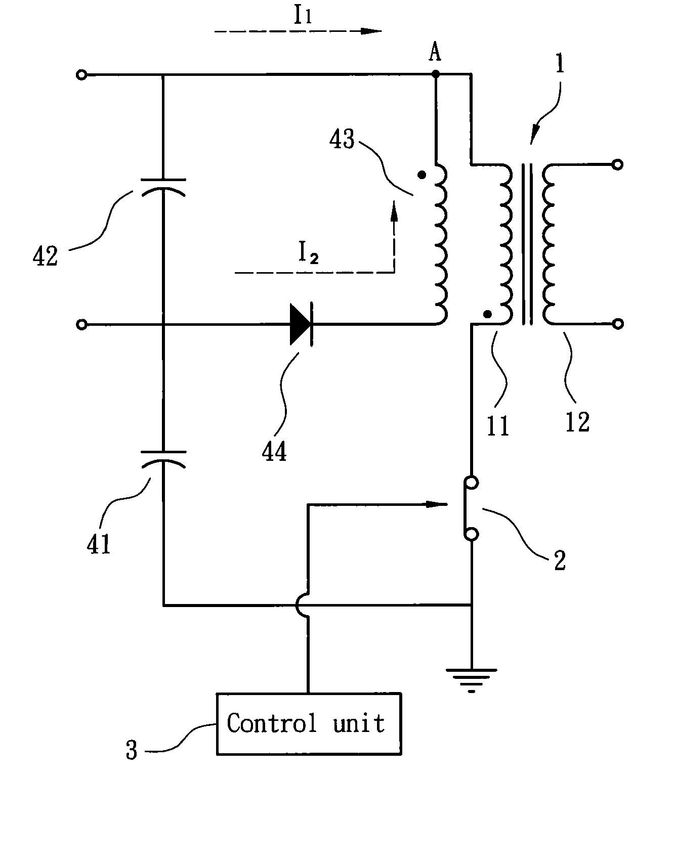
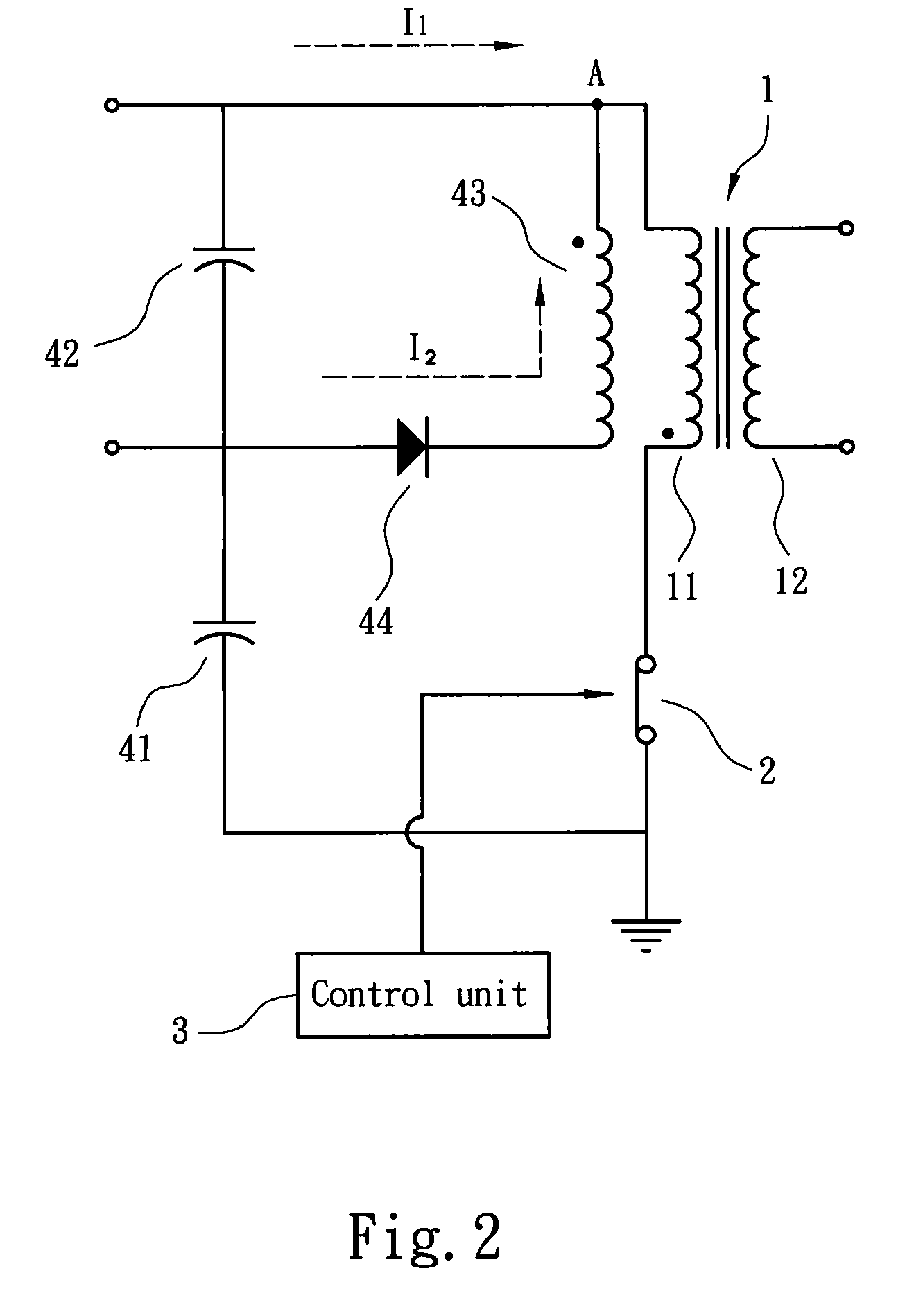
[0012]The present invention aims to provide a reverse energy recovery circuit in a power conversion circuit. Please refer to FIGS. 2 and 3 for an embodiment of the present invention. The power conversion circuit includes a transformer 1 which contains a primary winding side 11 and a secondary winding side 12. The primary winding side 11 is connected to a power switch 2 controlled by a control unit 3. The control unit 3 determines ON / OFF of the power switch 2 to further determine the cycle of input power passing through the primary winding side 11. The secondary winding side 12 generates an induction power through magnetic induction. The primary winding side 11 has a first end and a second end bridged by the reverse energy recovery circuit. The reverse energy recovery circuit comprises a first capacitor 41, a second capacitor 42, an ancillary winding 43 and a diode 44. The first and second capacitors 41 and 42 are coupled in series. The second capacitor 42 has one end connected to th...


PUM


Abstract

A reverse energy recovery circuit is located on a power conversion circuit equipped with a transformer which has a primary winding side connected to a power switch driven by a control unit. The primary winding side has a first end and a second end bridged by the reverse energy recovery circuit which comprises a first capacitor, a second capacitor, an ancillary winding and a diode. The first and second capacitors are coupled in series. The second capacitor has one end connected to the first end of the primary winding side. The ancillary winding has a first end connected to the first end of the primary winding side. The diode has a cathode connected to a second end of the ancillary winding and an anode bridged the first and second capacitors so that the diode and ancillary winding form a one way path between the first and second capacitors.

Description

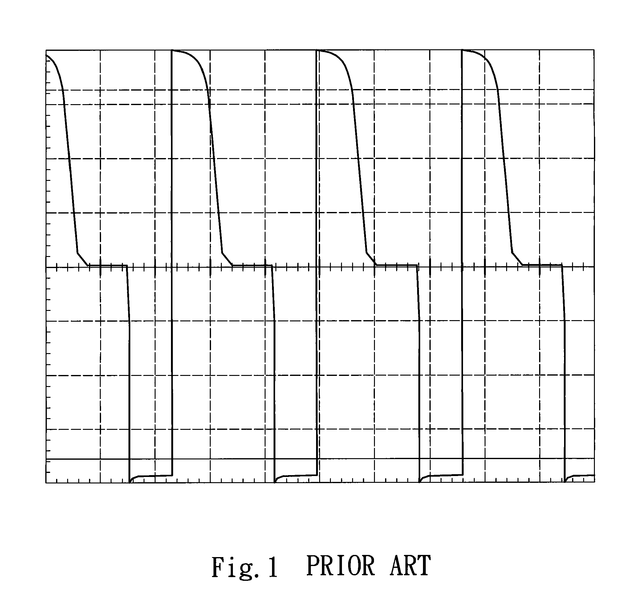
FIELD OF THE INVENTION[0001]The present invention relates to a reverse energy recovery circuit and particularly to a circuit adopted for use on a power conversion circuit equipped with a transformer to recover reverse surge energy generated by instantaneous switch at two ends of the transformer.BACKGROUND OF THE INVENTION[0002]Many electric devices at present are driven by a specific potential. Hence power conversion circuits are widely used to meet this purpose. Improvements are constantly made to achieve more stable output voltage and higher conversion efficiency. Power conversion is affected by many factors, such as loss of elements and loss caused by leakage or mutual offset when energy is transformed to magnetic force during power conversion. As a great amount of current passes through the transformer in the conversion circuit, leakage inductance stored in the transformer constantly stores energy and generates a reverse surge (shown by the front edge of square waveforms in FIG....

Claims


Application Information

Patent Timeline
Patent Type & Authority Patents(United States)
IPC IPC(8): H02M3/335
CPCH02M3/335H02M2001/346Y02B70/1491H02M1/346Y02B70/10
Inventor SHIH, YUNG-HSIANGKAN, CHUNG-PIN
Owner SPI ELECTRONICS
Learn More