Image calibration system and calibration method of a stereo camera

a calibration method and imaging technology, applied in image analysis, image enhancement, instruments, etc., can solve the problems of prior art inconvenient and time-consuming, the mechanism and optical accuracy of the above-mentioned stereo camera may not be maintained, and the distortion of the lens of the left/right eye image capture unit, etc., to achieve the effect of reducing the mechanism and optical accuracy of the stereo camera

Inactive Publication Date: 2015-04-16
EYS3D MICROELECTRONICS CO
View PDF2 Cites 93 Cited by
  • Summary
  • Abstract
  • Description
  • Claims
  • Application Information

AI Technical Summary

Benefits of technology

[0015]The present invention provides an image calibration system and a calibration method of a stereo camera. Because extrinsic parameters (or intrinsic parameters and the extrinsic parameters) of the stereo camera may shift due to a usage environment, a usage way, or a usage condition of the stereo camera after the stereo camera is shipped and operated for a period of time by a user, resulting in mechanism and optical accuracy of the stereo camera being reduced, the image calibration system and the calibration method provided by the present invention are suitable for the stereo camera which is shipped and operated for a period of time by the user. Because the present invention utilizes a calibration pattern with a plurality of feature points (printed in a board or displayed on a display) provided by a manufacturer of the stereo camera and the intrinsic parameters of the stereo camera to compensate shift of the extrinsic parameters of the stereo camera, and the present invention can also utilize a numerical optimization method provided by the prior art and the intrinsic parameters and the extrinsic parameters of the stereo camera to execute an automatic calibration operation on a left eye image capture unit and a right eye image capture unit of the stereo camera, compared to the prior art, the present invention is more convenient and inexpensive for the user and the user does not need a professional skill to execute the present invention.

Problems solved by technology

However, after the stereo camera is shipped, the above mentioned higher mechanism and optical accuracy required by the stereo camera may not be maintained due to a usage environment or a usage way of the stereo camera (e.g. the usage environment or the usage way of the stereo camera can change positions or capture image angles of left / right eye image capture units of the stereo camera, or make lenses of the left / right eye image capture units have distortion).
Thus, the prior art is inconvenient and time-consuming, and needs addition cost for the user.

Method used


Image

  • Image calibration system and calibration method of a stereo camera
  • Image calibration system and calibration method of a stereo camera
  • Image calibration system and calibration method of a stereo camera

Examples


first embodiment

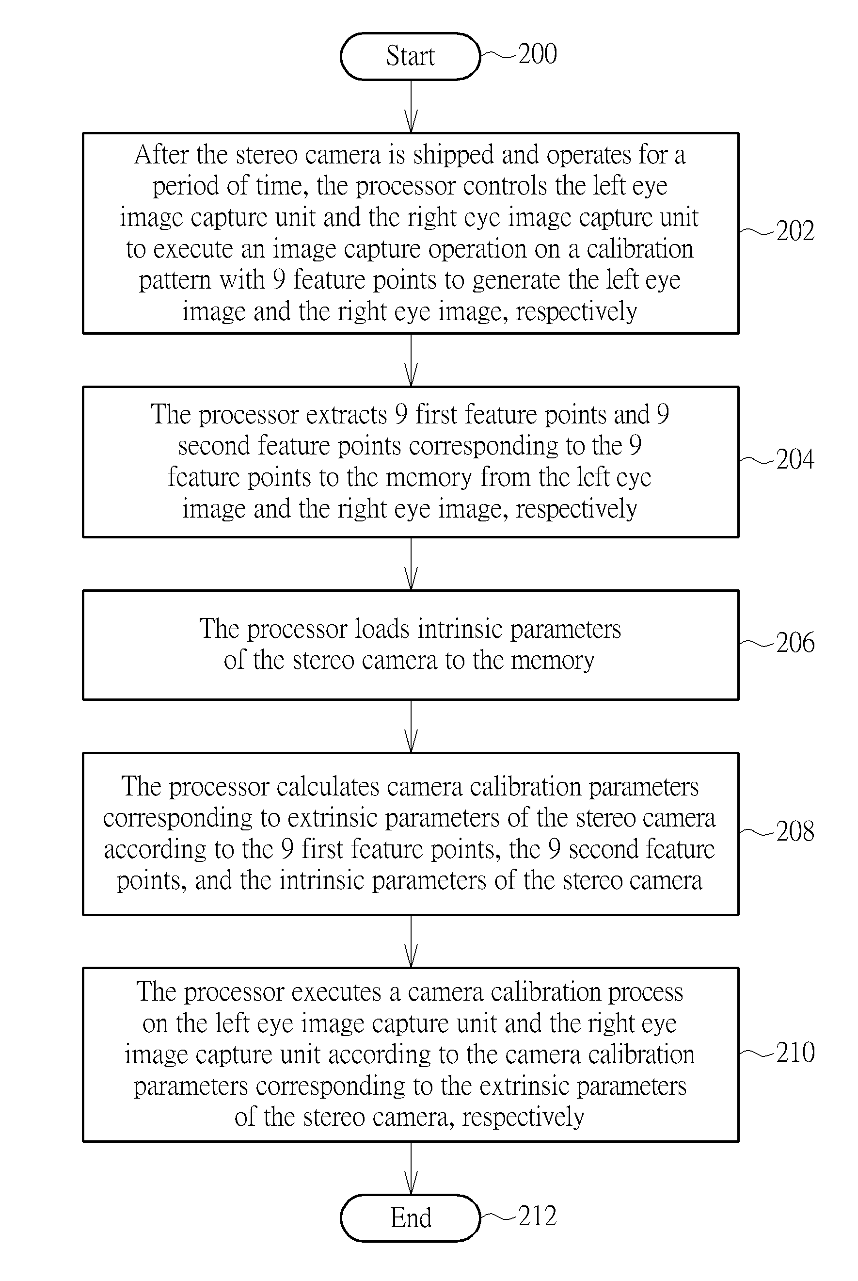
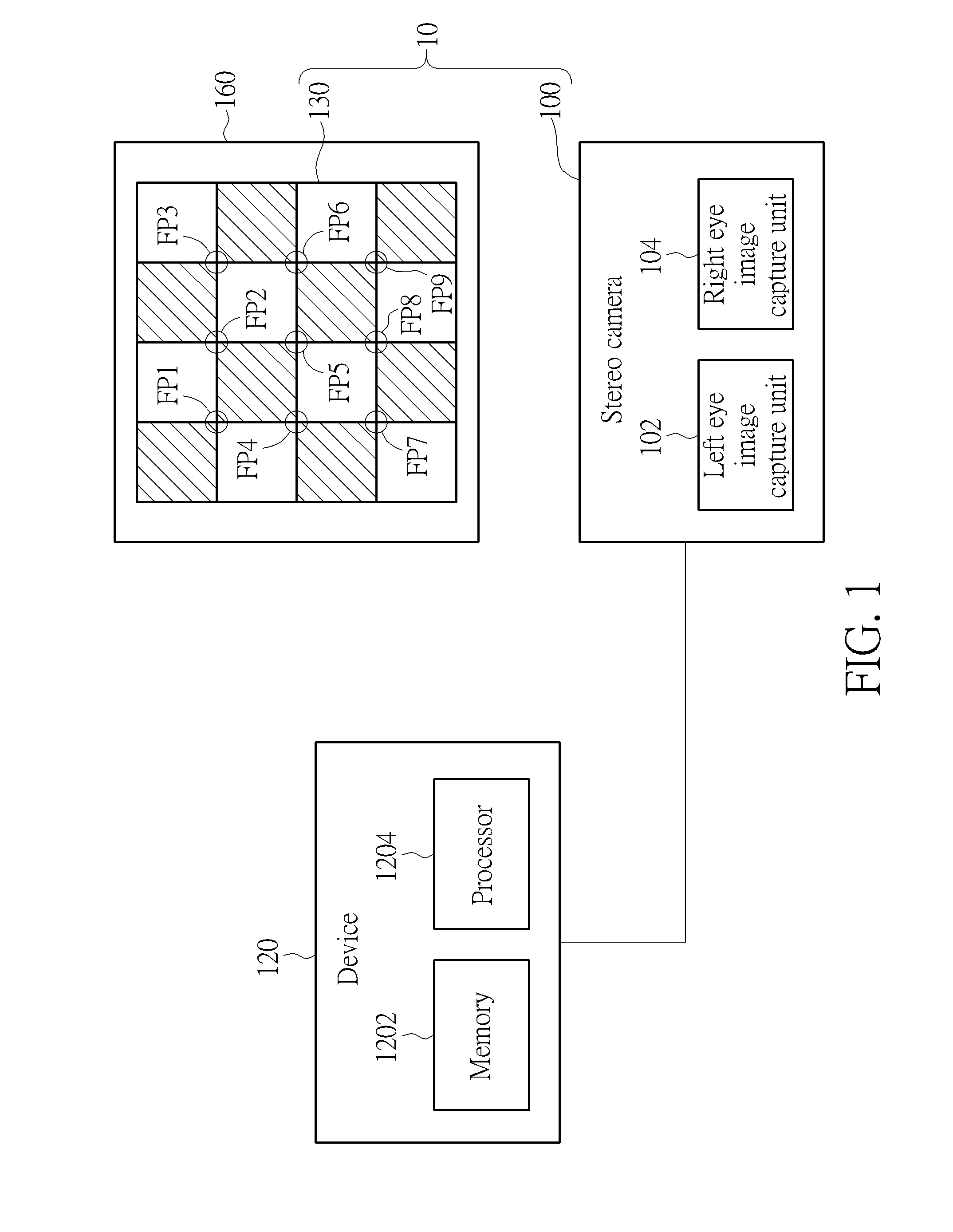
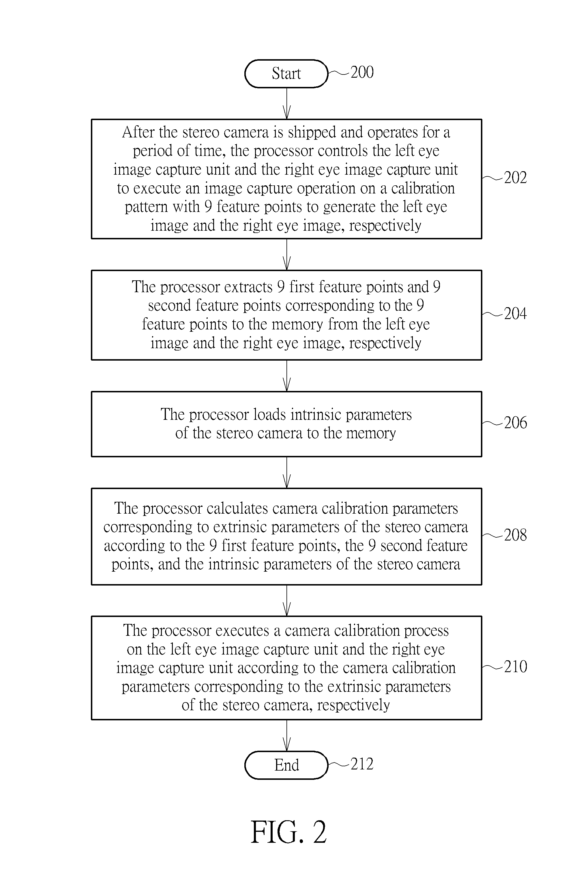
[0024]Please refer to FIG. 1. FIG. 1 is a diagram illustrating a stereo camera 100, a device 120, and a calibration pattern 130, wherein the stereo camera 100 and the calibration pattern 130 are included in an image calibration system 10, the stereo camera 100 includes a left eye image capture unit 102 and a right eye image capture unit 104, and the device 120 includes a memory 1202 and a processor 1204. Please refer to FIGS. 2-4. FIG. 2 is a flowchart illustrating a calibration method of a stereo camera FIG. 3 is a diagram illustrating a left eye image 140, and FIG. 4 is a diagram illustrating a right eye image 150. The calibration method in FIG. 2 is illustrated using the image calibration system 10 and the device 120 in FIG. 1. Detailed steps are as follows:

[0025]Step 200: Start.

[0026]Step 202: After the stereo camera 100 is shipped and operates for a period of time, the processor 1204 controls the left eye image capture unit 102 and the right eye image capture unit 104 to execu...

second embodiment

[0033]Please refer to FIGS. 1, 3, 4, 6. FIG. 6 is a flowchart illustrating a calibration method of a stereo camera according to a The calibration method in FIG. 6 is illustrated using the image calibration system 10 and the device 120 in FIG. 1. Detailed steps are as follows:

[0034]Step 600: Start.

[0035]Step 602: After the stereo camera 100 is shipped and operates for a period of time, the processor 1204 controls the left eye image capture unit 102 and the right eye image capture unit 104 to execute an image capture operation on the calibration pattern 130 with the 9 feature points FP1-FP9 to generate a plurality of left eye images and a plurality of right eye images, respectively.

[0036]Step 604: The processor 1204 executes a noise reduction operation on the plurality of left eye images and the plurality of right eye images, respectively.

[0037]Step 606: The processor 1204 extracts a plurality of first feature points and a plurality of second feature points corresponding to the 9 fea...

third embodiment

[0043]Please refer to FIGS. 1, 7. FIG. 7 is a flowchart illustrating a calibration method of a stereo camera according to a The calibration method in FIG. 7 is illustrated using the image calibration system 10 and the device 120 in FIG. 1. Detailed steps are as follows:

[0044]Step 700: Start.

[0045]Step 702: After the stereo camera 100 is shipped and operates for a period of time, the processor 1204 controls the left eye image capture unit 102 and the right eye image capture unit 104 to execute an image capture operation on the calibration pattern 130 with the 9 feature points FP1-FP9 to generate a plurality of left eye images and a plurality of right eye images, respectively.

[0046]Step 704: The processor 1204 executes a noise reduction operation on the plurality of left eye images and the plurality of right eye images, respectively.

[0047]Step 706: The processor 1204 extracts a plurality of first feature points and a plurality of second feature points corresponding to the 9 feature p...


PUM


Abstract

A calibration method of a stereo camera includes controlling a left eye image capture unit and a right eye image capture unit of the stereo camera to execute an image capture operation on a calibration pattern with a plurality of feature points to generate a left eye image and a right eye image, respectively; extracting a plurality of first feature points and a plurality of second feature points corresponding to the plurality of feature points from the left eye image and the right eye image, respectively; calculating camera calibration parameters corresponding to extrinsic parameters of the stereo camera according to the plurality of first feature points, the plurality of second feature points, and intrinsic parameters of the stereo camera; and executing an camera calibration process on the left eye image capture unit and the right eye image capture unit according to the camera calibration parameters, respectively.

Description

CROSS REFERENCE TO RELATED APPLICATIONS[0001]This application claims the benefit of U.S. Provisional Application No. 61 / 890,342, filed on Oct. 14, 2013 and entitled “Stereo Camera Calibration,” the contents of which are incorporated herein by reference.BACKGROUND OF THE INVENTION[0002]1. Field of the Invention[0003]The present invention relates to an image calibration system and a calibration method of a stereo camera, and particularly to an image calibration system and a calibration method of a stereo camera that can utilize a calibration pattern with a plurality of feature points provided by a manufacturer of the stereo camera and intrinsic parameters of the stereo camera to compensate shift of extrinsic parameters of the stereo camera.[0004]2. Description of the Prior Art[0005]To make a stereo camera generate good quality three-dimensional images, the stereo camera usually needs higher mechanism and optical accuracy, wherein before the stereo camera is shipped, a manufacturer of ...

Claims


Application Information

Patent Timeline
Patent Type & Authority Applications(United States)
IPC IPC(8): H04N13/02
CPCH04N13/0246H04N13/0239G06T7/85G06T2207/30208
Inventor HO, MING-CHELIN, WEN-KUO
Owner EYS3D MICROELECTRONICS CO
Why Eureka
Try Eureka