
Image processing device, moving-image processing device, video processing device, image processing method, video processing method, television receiver, program, and recording medium

Inactive Publication Date: 2015-04-16
SHARP KK
View PDF8 Cites 18 Cited by
  • Summary
  • Abstract
  • Description
  • Claims
  • Application Information

AI Technical Summary

Benefits of technology

The present invention is an image processing device that can smoothly blur an image based on its features. This helps to make the image look more natural and smooth.

Problems solved by technology

However, the following problem arises: although intensification of smoothing for reducing the block noise suppresses deterioration of display quality of a video in which block noise is noticeable, the intensification of smoothing results in blurring of a video in which block noise is unnoticeable, and therefore causes a reduction in display quality of the video.

Method used


Image

  • Image processing device, moving-image processing device, video processing device, image processing method, video processing method, television receiver, program, and recording medium
  • Image processing device, moving-image processing device, video processing device, image processing method, video processing method, television receiver, program, and recording medium
  • Image processing device, moving-image processing device, video processing device, image processing method, video processing method, television receiver, program, and recording medium

Examples


embodiment 1

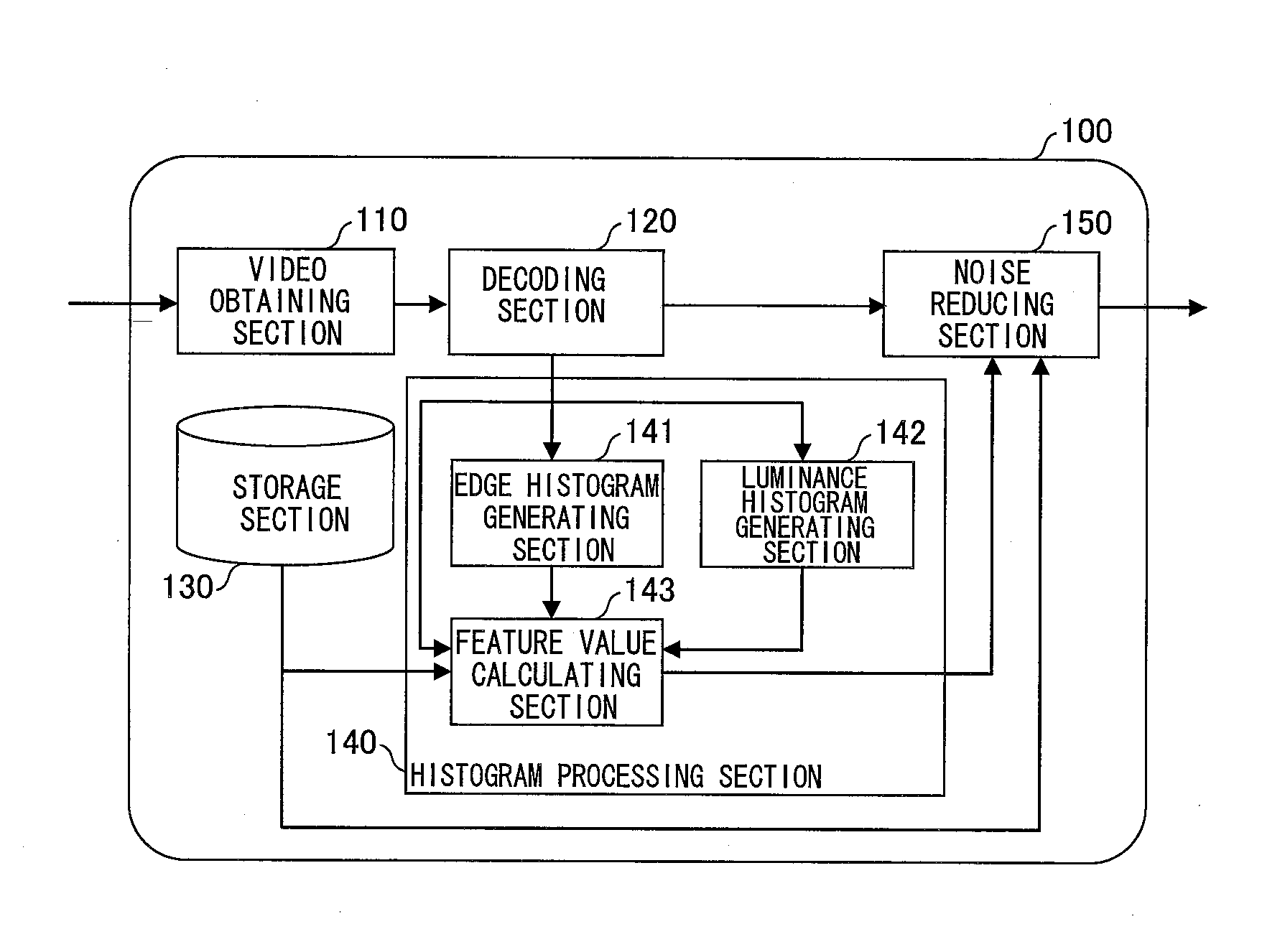
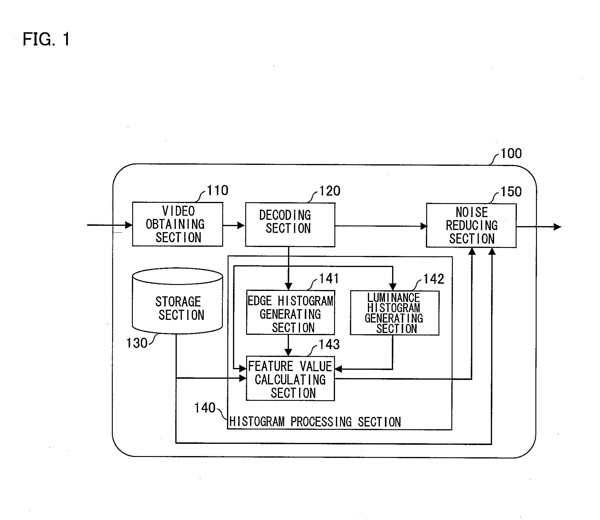
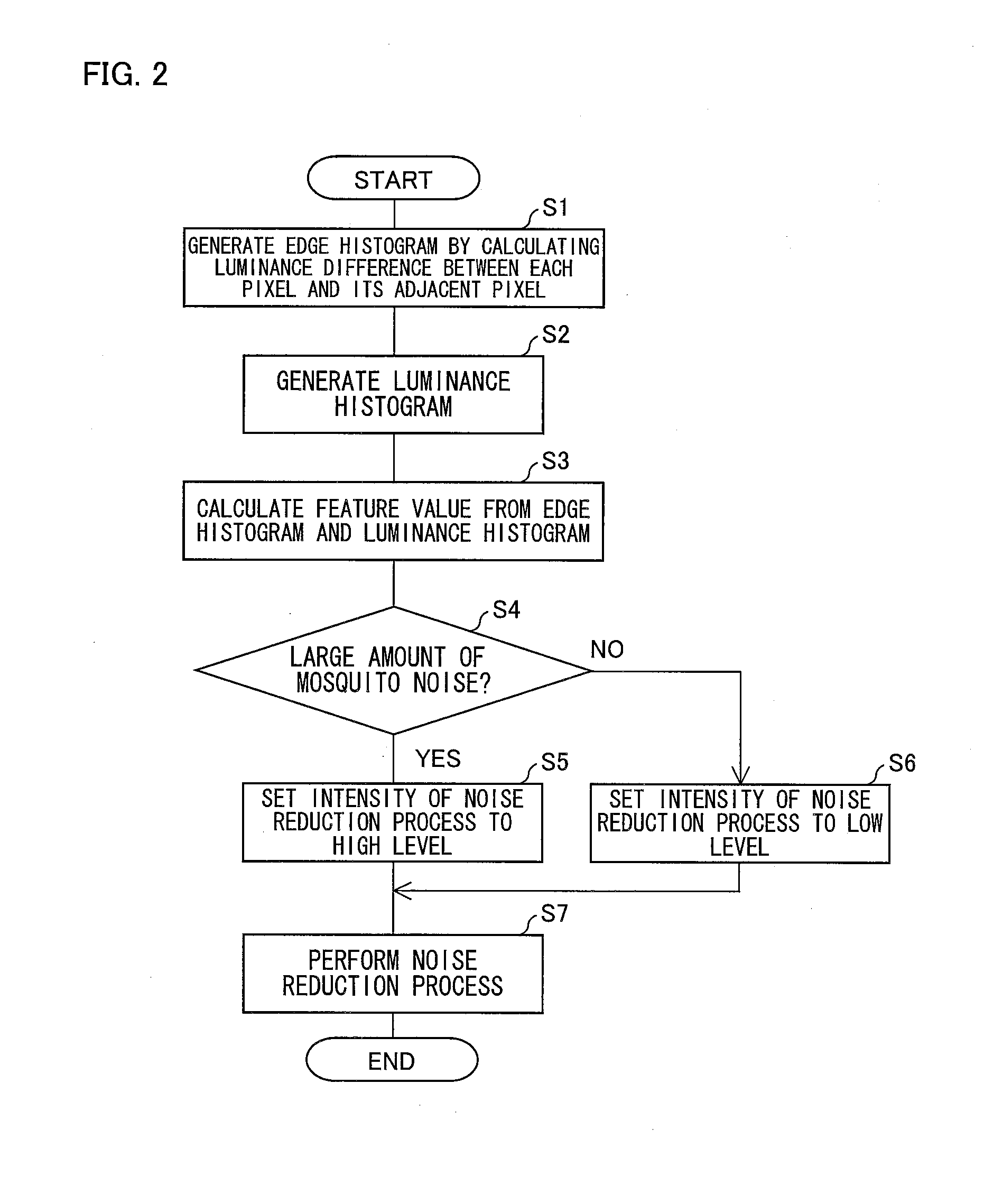
[0029]A video processing device in accordance with one embodiment of the present invention is equipped with a function (noise reduction (NR) function) to reduce mosquito noise in a video (moving image) based on a video signal that has been inputted. Specifically, the video processing device of Embodiment 1 is configured such that whether a target decoded image of decoded images each obtained by decoding a video signal is subjected to a high-intensity noise reduction process (specifically, smoothing process) or to a low-intensity noise reduction process is determined in accordance with (i) an edge histogram (corresponding to “first frequency distribution data” recited in the Claims) of the target decoded image and (ii) a luminance histogram (corresponding to “second frequency distribution data” recited in the Claims) of the target decoded image.

[0030]The following description will discuss, with reference to the drawings, the details of the video processing device in accordance with E...

embodiment 2

[0097]The following description will discuss a video processing device in accordance with another embodiment of the present invention. The video processing device of Embodiment 2 is also equipped with a function to reduce mosquito noise in a video (moving image) based on a video signal that has been inputted. Note, however, that the video processing device of Embodiment 2 differs from the video processing device 100 of Embodiment 1 in that the video processing device of Embodiment 2 is configured to determine, based only on an edge histogram of a target decoded image, whether the target decoded image (each decoded image) obtained by decoding a video signal is to be subjected to a high-intensity noise reduction process or to a low-intensity noise reduction process.

[0098]The details of the video processing device of Embodiment 2 will be described below with reference to the drawings.

[0099]First, a configuration of the video processing device will be described with reference to FIG. 5....

embodiment 3

[0115]The following description will discuss a video processing device in accordance with a further embodiment of the present invention. The video processing device of Embodiment 3 is also equipped with a function to reduce mosquito noise in a video (moving image) based on a video signal that has been inputted. Note, however, that the video processing device of Embodiment 3 differs from the video processing devices of Embodiments 1 and 2 in that an intensity of a noise reduction process to be carried out on a decoded image is adjusted in accordance with a factor other than a histogram.

[0116]The details of the video processing device of Embodiment 3 will be described below with reference to the drawings.

[0117]First, a configuration of the video processing device will be described below with reference to FIG. 6. FIG. 6 is a block diagram illustrating a main configuration of a video processing device 100″ in accordance with Embodiment 3. As illustrated in FIG. 6, the video processing d...


PUM


Abstract

A video processing device (100) includes: an edge histogram generating section (141) and a noise reducing section (150). The generating section (141) generates an edge histogram of a decoded image obtained from a video signal. The noise reducing section (150) (i) determines whether or not a ratio of a sum of frequencies of classes higher than a predetermined class of an edge histogram to a sum of all frequencies the edge histogram is equal to or greater than a predetermined threshold value and (ii) performs a smoothing process on the decoded image with a smoothing intensity adjusted in accordance with whether or not the ratio is equal to or greater than the predetermined threshold value.

Description

TECHNICAL FIELD[0001]The present invention mainly relates to an image processing device and to an image processing method, each of which is intended for improving the quality of a moving image and / or a still image.BACKGROUND ART[0002]Conventionally, there have been various technologies developed for improving the quality of a video.[0003]Patent Literature 1 discloses a luminance conversion device developed with the aim of properly highlighting contrast of even a person whose image is captured in front of a wall surface of a building, which wall surface has little luminance variation. The luminance conversion device of Patent Literature 1 is configured to (i) obtain (a) a luminance histogram indicative of the respective numbers of pixels of input images in different luminances and (b) an edge histogram indicative of the respective numbers of edges in the different luminances and (ii) convert the luminance of an input image by use of the two histograms.[0004]There has also been a tech...

Claims


Application Information

Patent Timeline
IPC IPC(8): G06T5/00H04N5/14G06T5/40H04N9/64H04N5/21
CPCG06T5/002H04N9/646H04N5/21G06T5/40H04N5/142G06T2207/10004G06T2207/10016G06T2207/10024G06T2207/20182G06T2207/20012G06T5/90G06T5/70
Inventor WATANABE, MIHOKOKOIKE, AKIRAKOHNO, YOSHINORITANIGUCHI, SHIGEKITAKIGUCHI, MASAHIKOMIZOBUCHI, ICHIRO
Owner SHARP KK
Learn More