Automatically travelling device and control method therefor

a technology of automatic moving and control method, which is applied in the direction of propulsion by capacitors, safety/protection circuits, instruments, etc., can solve the problems of battery pack damage, continuous movement and damage, and possible damag

Active Publication Date: 2015-04-16
POSITEC POWER TOOLS (SUZHOU) CO LTD
View PDF7 Cites 17 Cited by
  • Summary
  • Abstract
  • Description
  • Claims
  • Application Information

AI Technical Summary

Problems solved by technology

However, the battery pack may become damaged due to over-discharging.
However, due to complicated environments in many working areas and some unexpected cases occurring in the working and returning, difficulties may occur when the automatic moving device returns to the charging station

Method used


Image

  • Automatically travelling device and control method therefor
  • Automatically travelling device and control method therefor
  • Automatically travelling device and control method therefor

Examples


Embodiment Construction

[0110]The detailed description and technical details of the invention, along with the appended drawings, are as follows. The drawings are only for reference and description and not for limitation of the invention.

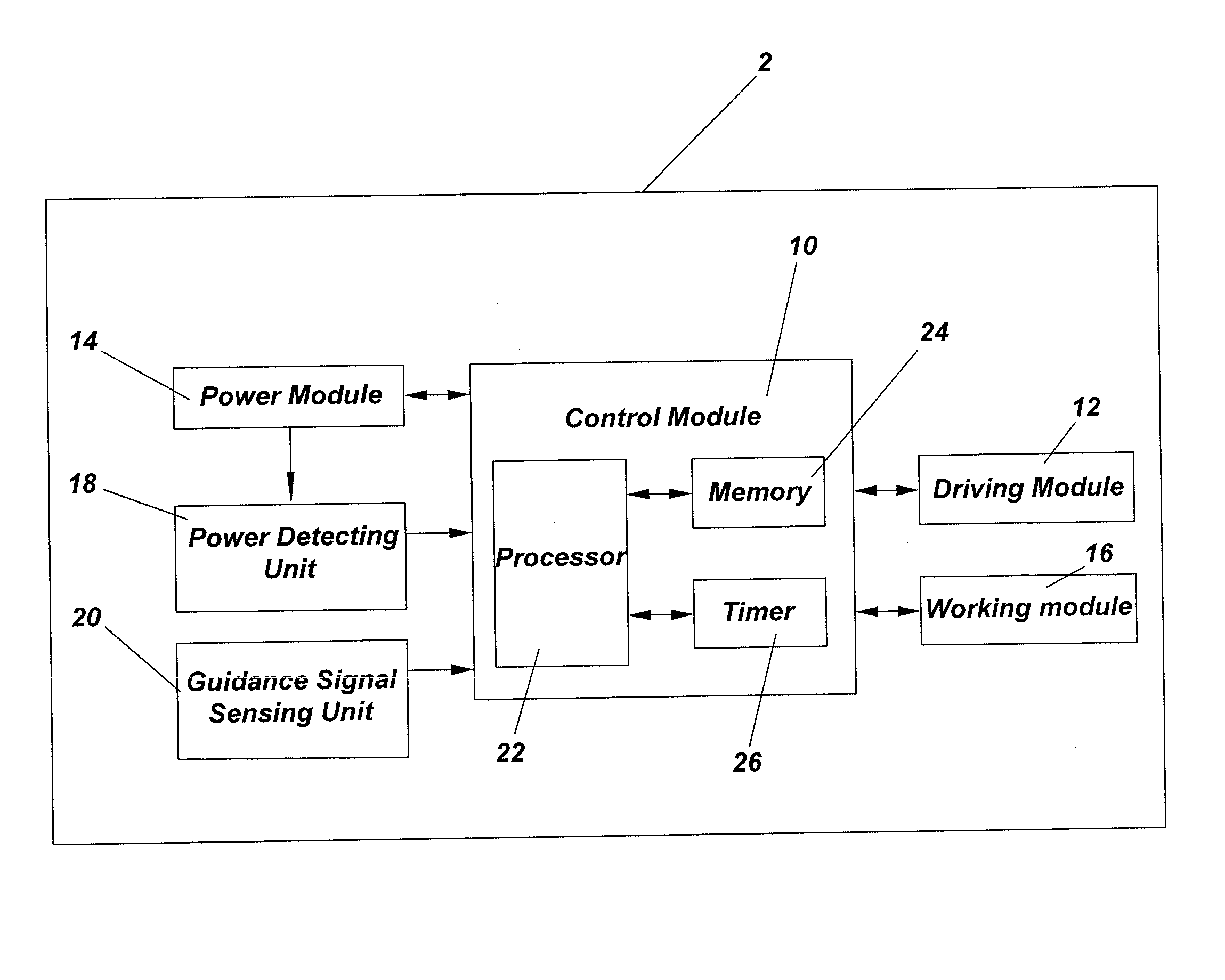
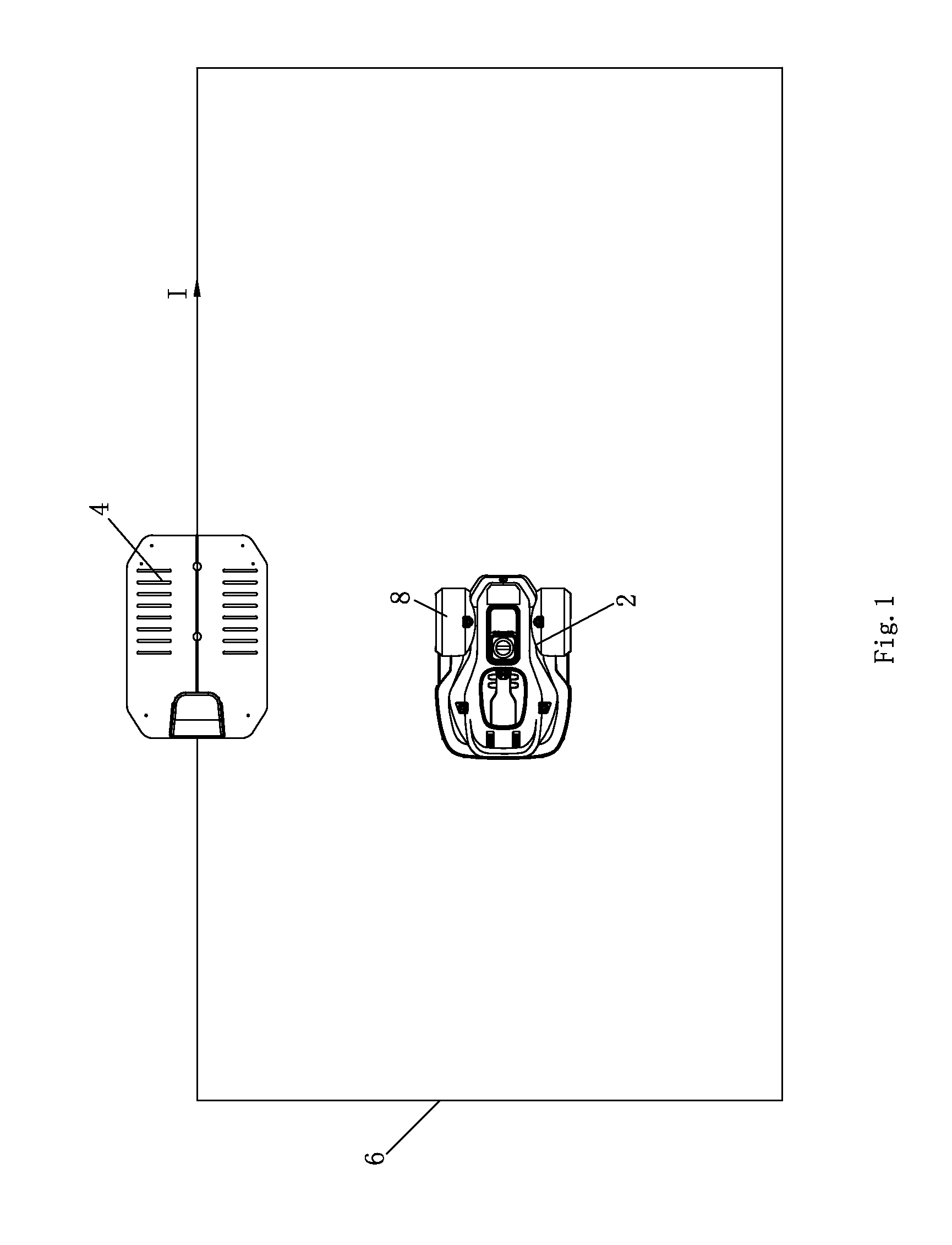
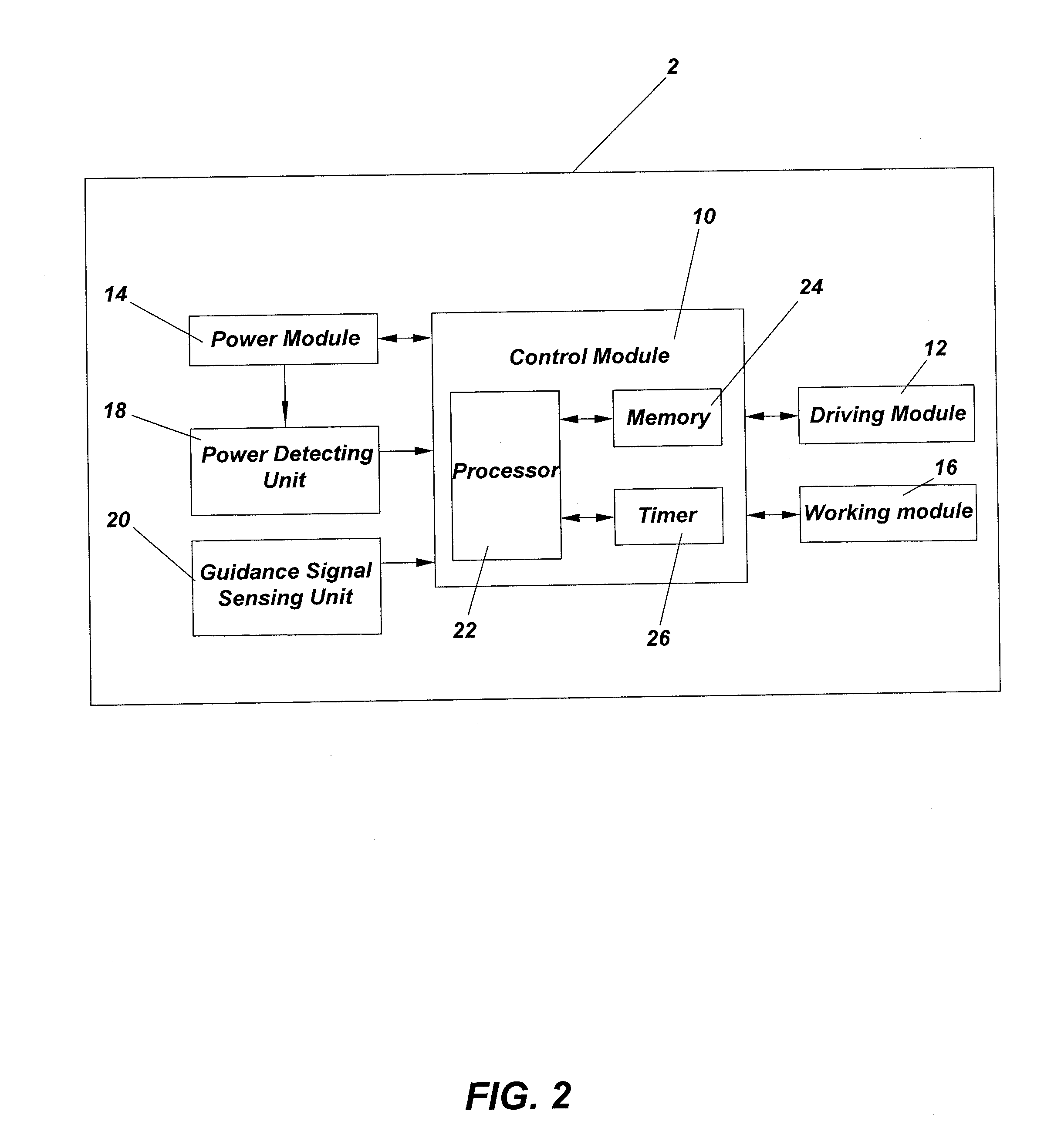
[0111]FIG. 1 shows a schematic drawing of the working system of the automatic moving device in an embodiment of the invention. The working system of the automatic moving device includes the automatic moving device 2, charging station 4 and charging guide line 6 for a guidance signal-transmitting unit at returning and connecting with the charging station 4. In this implementation example, the charging guide line 6 is drawn out from the charging station 4 and returned to charging station 4 after making a loop around the operating range of the automatic moving device 2 and forming a boundary line for the working system of the automatic moving device 2. The working area is within the area enclosed by the charging guide line 6 and the non-working area is outside the area enclose...


PUM


Abstract

An automatic moving device and a control method therefor. The automatic moving device comprises a battery pack providing power. The automatic moving device can work within a working area and automatically return to a charging station for charging. The control method comprises the following steps: monitoring the power level of the battery pack; if the power level of the battery pack is less than or equal to a preset power level, initiating an action of returning the automatic moving device to the charging station; and after a preset time period, stopping the travel. By setting a preset time period simultaneously with initiating a return action, and executing a return action within the preset time period, the control method prevents damage to the battery pack from over-discharging caused by the automatic moving device continually returning, thus achieving the effects of protecting the battery pack and extending the life thereof.

Description

CROSS-REFERENCE TO RELATED APPLICATIONS[0001]This application is a national phase entry under 35 U.S.C. §371 of International Patent Application PCT / CN2013 / 072003, filed Feb. 28, 2013, designating the United States of America and published in Chinese as International Patent Publication WO 2013 / 127350 A1 on Sep. 6, 2013, which claims the benefit under Article 8 of the Patent Cooperation Treaty and under 35 U.S.C. §119(e) to Chinese Application Serial Nos. 2012 / 10052429.6 2012, filed Mar. 2, 2012, 2012 / 10052428.1 2012, filed Mar. 2, 2012, and 2012 / 10261668.2 2012, filed Jul. 26, 2012, the disclosure of each of which is hereby incorporated herein in its entirety by this reference.TECHNICAL FIELD[0002]The invention relates to an automatic moving device, and more particularly, to an automatic moving device with over-discharging protection from a battery pack during the returning to charge process.[0003]The invention also relates to a control method for the automatic moving device, and mo...

Claims


Application Information

Patent Timeline
IPC IPC(8): B25J9/00
CPCB25J9/0003Y10S901/01Y10S901/49A01D69/02A01D34/008G05D1/0225B60L3/0046B60L15/2036B60L2200/40B60L2220/46B60L2240/12B60L2240/421B60L2240/545B60L2240/547B60L2240/549B60L2240/80B60L2250/16B60L2260/32Y02T10/7072Y02T90/14Y02T10/72Y02P90/60B60L53/14B60L50/40B60L50/52B60L58/14B60L58/13B60L58/21H02J7/00306B60L58/16B60L58/15B60L53/305Y02T10/64Y02T10/70Y02T90/16Y02T90/12B25J9/1664B25J9/1674B25J11/0085B25J19/005
Inventor MOU, GUOLIANGTIAN, JIAOFENGSHENG, XIAOCHUWU, HONGBINGSONG, DONGJING
Owner POSITEC POWER TOOLS (SUZHOU) CO LTD
Why Eureka
Try Eureka