Elastic-deformation-compensation control device and control method for articulated robot
- Summary
- Abstract
- Description
- Claims
- Application Information
AI Technical Summary
Benefits of technology
Problems solved by technology
Method used
Image
Examples
first embodiment
General Configuration
[0041]First, an overview of a vertical articulated robot (hereinafter, occasionally merely referred to as articulated robot), to which an elastic-deformation-compensation control device according to this embodiment is applied, is described.
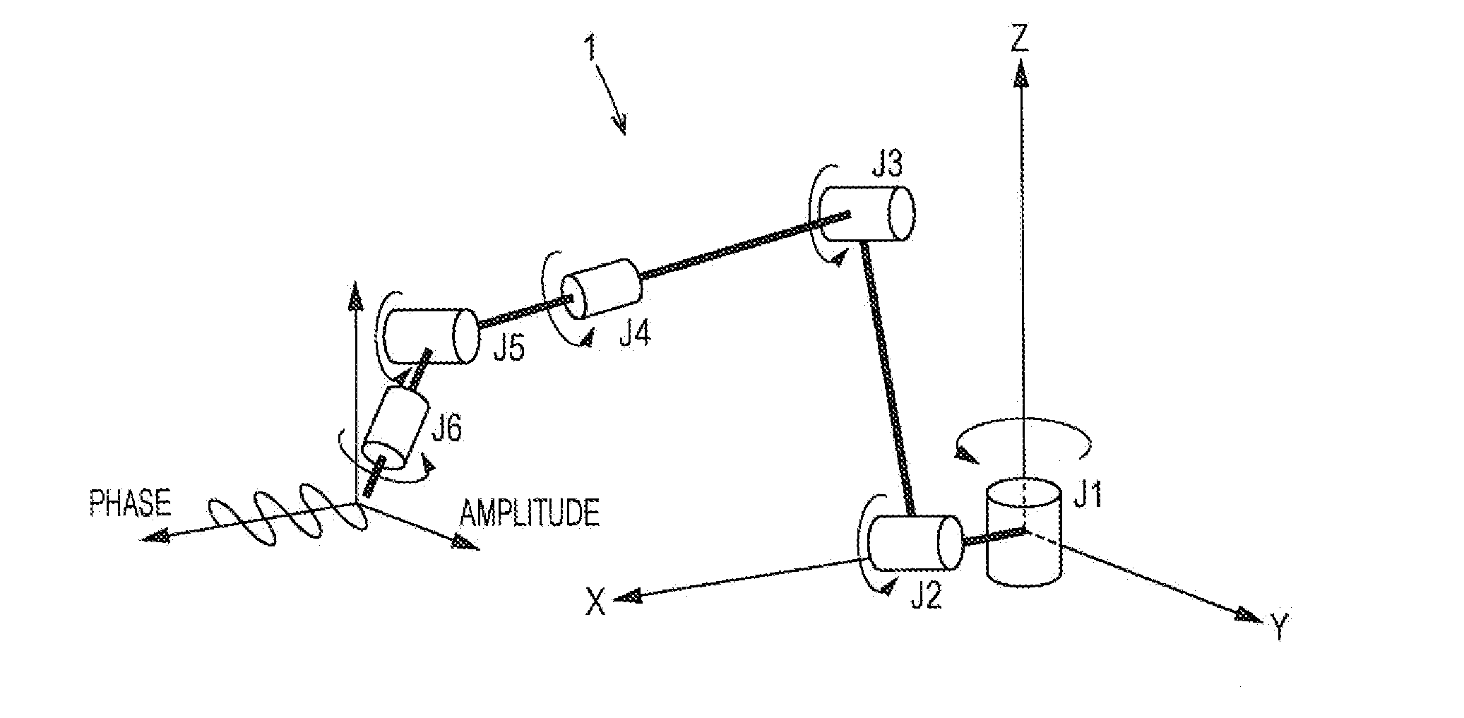
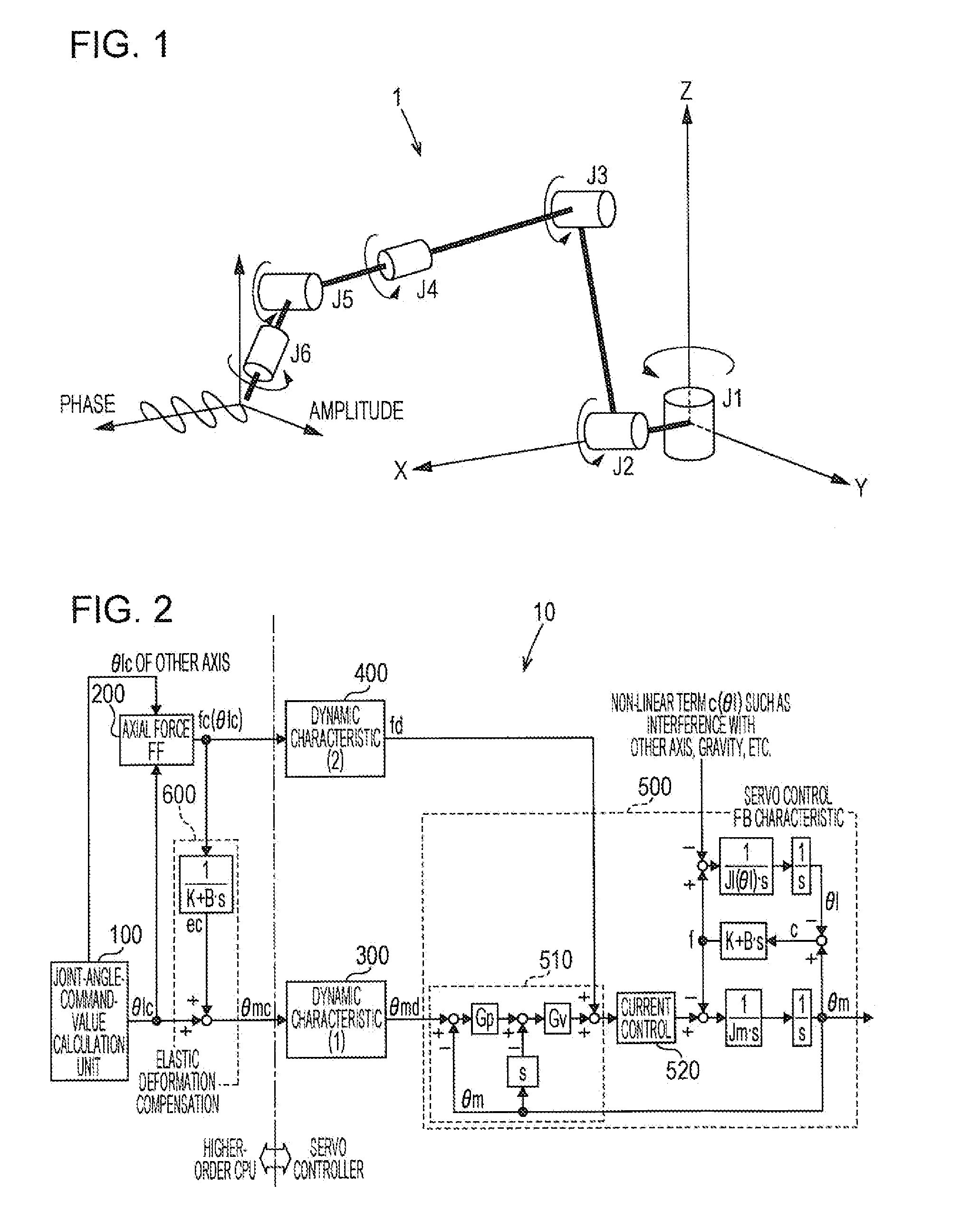
[0042]FIG. 1 is an example of a robot that causes a welding torch to perform a tilting operation (weaving operation). FIG. 1 shows an overview of an articulated robot 1 to which the elastic-deformation-compensation control device according to this embodiment is applied. The articulated robot 1 is a vertical articulated type, and includes six joints J1 to J6. A welding torch is provided at a distal end of the axis of J6, a welding wire is fed from the welding torch, and hence arc welding is executed with the welding wire. In the articulated robot 1, an area between predetermined welding start point and welding end point is set as a welding work section. The articulated robot 1 is set to cause the welding wire to perform a tilti...
second embodiment
Modification of Second Embodiment
[0081]Next, an elastic-deformation-compensation control device according to a modification of the second embodiment of the invention is described below.
[0082]As described above, the characteristic of the second dynamic characteristic calculation unit 400 is given as a desirable dynamic characteristic (having a very high high-frequency cutoff characteristic). However, if the current control characteristic of the motor-current control unit 520 is not negligible, the characteristic of the second dynamic characteristic calculation unit 400 is given as a characteristic obtained by dividing the desirable dynamic characteristic by the current control characteristic. This represents that, if the current control characteristic of the motor-current control unit 520 is considered, the characteristic of the first dynamic characteristic calculation unit 300 is given to correspond to a characteristic obtained by dividing the characteristic in the second dynamic ch...
third embodiment
[0087]An elastic-deformation-compensation control device according to a third embodiment of the invention is described below. The elastic-deformation-compensation control device according to this embodiment differs from the elastic-deformation-compensation control device 10 according to the above-described first embodiment in the method of giving the first dynamic characteristic calculation unit 300. Other configuration is similar to that of the first embodiment, and hence the part redundant to the above-described configuration is not repeated this time.
[0088]If it is considered that good performance can be obtained although the current control characteristic is approximated to 1 for very high speed response, Expression (1) is modified to Expression (5) as follows.
Gp·Gv·s+Gp·GiJm·s3+Gv·s2+(Gp·Gv+Gi)·s+Gp·Gi(5)
[0089]Expression (2) that gives the first dynamic characteristic calculation unit 300 is modified to Expression (6) as follows.
dynamiccharacteristic2 / servoFBcontroldynamicchara...
PUM
| Property | Measurement | Unit |
|---|---|---|
| Phase | aaaaa | aaaaa |
Abstract
Description
Claims
Application Information
 - R&D
- Intellectual Property
- Life Sciences
- Materials
- Tech Scout
- Unparalleled Data Quality
- Higher Quality Content
- 60% Fewer Hallucinations
Browse by: Latest US Patents, China's latest patents, Technical Efficacy Thesaurus, Application Domain, Technology Topic, Popular Technical Reports.
© 2025 PatSnap. All rights reserved.Legal|Privacy policy|Modern Slavery Act Transparency Statement|Sitemap|About US| Contact US: help@patsnap.com


