
Snow Plow Blade Detection and Compensation System

a technology of compensation system and snow plow blade, which is applied in the field of snow plow system for vehicles, can solve the problems of changing the cooling characteristics of the powertrain, system not commonly integrated into the vehicle control system,

Inactive Publication Date: 2015-04-16
FORD GLOBAL TECH LLC
View PDF2 Cites 10 Cited by
  • Summary
  • Abstract
  • Description
  • Claims
  • Application Information

AI Technical Summary

Benefits of technology

The present invention is a system that detects and compensates for the use of a snow plow blade on a vehicle. This system can detect when the plow blade is attached to the vehicle and when it is actually being used in plowing mode. The system can use various methods such as computer vision, proximity sensing, direct input, drive pattern recognition, and audio recognition to determine the plow blade status. The system can make appropriate adjustments to the vehicle's braking, steering, and powertrain systems to compensate for the altered performance of the vehicle. This system improves the efficiency and effectiveness of snow plowing vehicles in various snow and weather conditions.

Problems solved by technology

However, these systems are not commonly integrated into the vehicle control system.
Some areas of the vehicle control system that may be affected by installation and usage of a plow blade are: (1) the plow blade presence may alter the center of gravity of the vehicle by dramatically increasing the mass over the front axle, thereby changing the vehicle dynamics characteristics (e.g., braking, cornering, accelerating, and / or the like); and (2) airflow, i.e., the plow blade, when raised, may obstruct the designed airflow over the radiator and transmission cooler, for example, thereby potentially changing the powertrain cooling characteristics.

Method used


Image

  • Snow Plow Blade Detection and Compensation System
  • Snow Plow Blade Detection and Compensation System
  • Snow Plow Blade Detection and Compensation System

Examples


Embodiment Construction

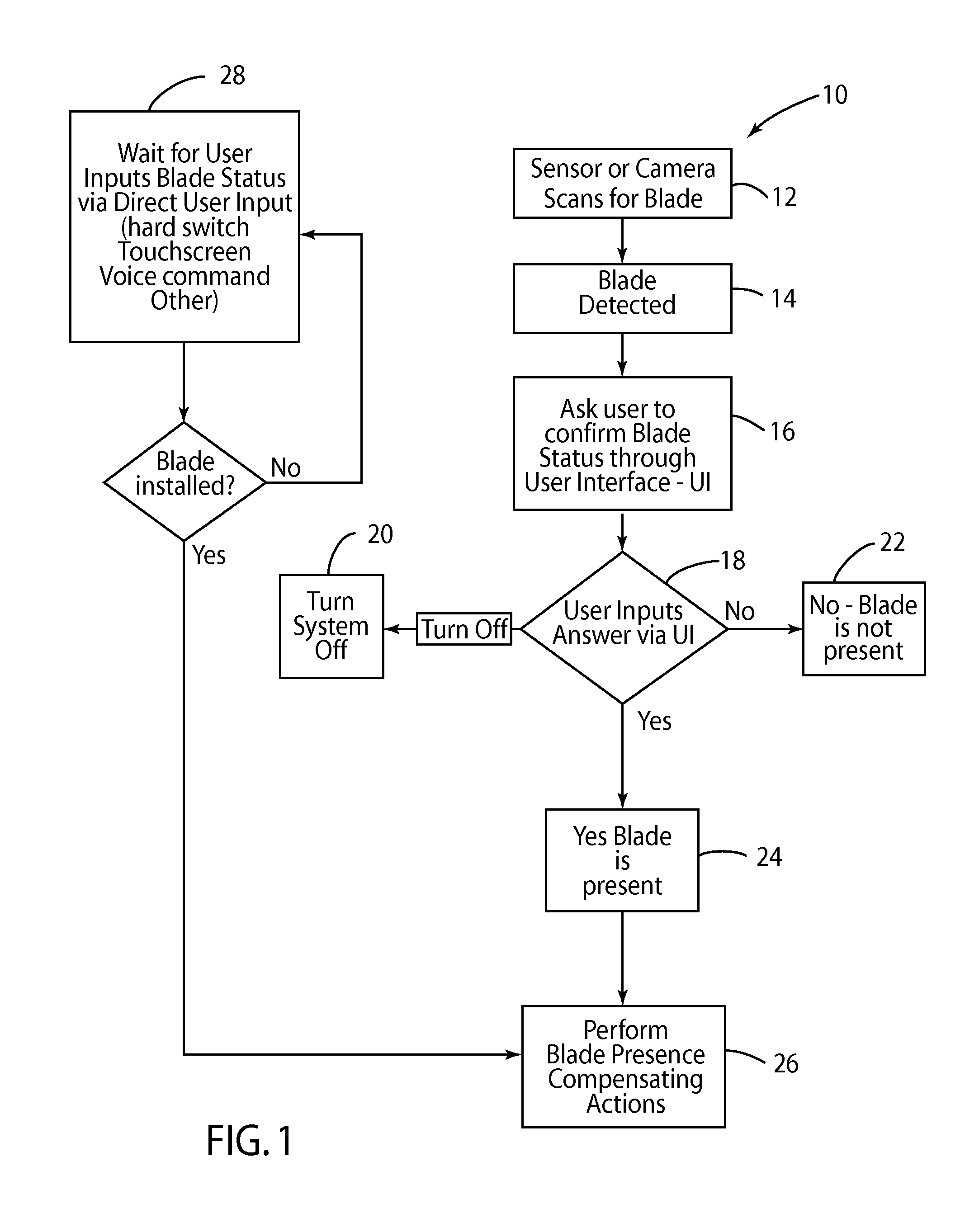
[0019]FIG. 1 shows a system flowchart, seen generally at 10, which details several examples of plow blade presence detection methods that may be used either alone or in combination.

[0020]At step 12, a sensor or camera mounted at or near a front portion of the vehicle scans for the presence of a plow blade. At step 14, a plow blade is detected. At step 16, the system 10 asks the user / driver to confirm the plow blade status (e.g., if a plow blade is indeed present on the front of the vehicle) through a user interface, described in more detail herein. At decision node 18, the user / driver is able to input an answer to the query regarding the plow blade status via the user interface. Decision node 18 can result in three different outcomes. In the first outcome, the user / driver can turn the system 10 off, as shown at step 20. In the second outcome, the user / driver can answer in the negative, i.e., a plow blade is not present, as shown at step 22. In the third outcome, the user / driver can ...


PUM


Abstract

A snow plow blade detection and compensation system and method operable to detect when a plow blade is attached to the vehicle and then, when the driver is in plowing mode, take appropriate compensating actions. The systems and methods may include: (1) computer vision based recognition of plow blade position, wherein object recognition from a forward looking camera and computer vision system may be installed on the vehicle to recognize that the plow blade is in the down position; (2) proximity sensing system indicating that the plow blade is down, wherein multiple sensors may be used to indicate that the plow blade position is down; (3) direct input of plowing status, wherein vehicle Interfaces indicate that a plow mode is active; (4) drive pattern recognition; and / or (5) audio recognition, wherein microphones detect sound characteristics of “scraping” sounds, inferring that the plow blade is on the ground and pushing snow.

Description

CROSS-REFERENCE TO RELATED APPLICATIONS[0001]Not Applicable.BACKGROUND OF THE INVENTION[0002]1. Field of the Invention[0003]The present invention relates generally to snow plow systems for vehicles; and, more specifically to detection and compensation systems for vehicles that use snow plow systems.[0004]2. Description of Related Art[0005]In colder climates vehicles are commonly used to plow snow. Vehicle owners typically install aftermarket snow plowing systems that may include an electrically powered plow blade at the front of the vehicle. Other equipment may also be installed, such as lights, salt spreaders and / or dump boxes, all which may have an effect on the vehicle control system. However, these systems are not commonly integrated into the vehicle control system.[0006]Some areas of the vehicle control system that may be affected by installation and usage of a plow blade are: (1) the plow blade presence may alter the center of gravity of the vehicle by dramatically increasing ...

Claims


Application Information

Patent Timeline
Patent Type & Authority Applications(United States)
IPC IPC(8): B60W10/00B60W10/20B60W10/30B60W10/18
CPCB60W10/00B60W10/18B60W10/20B60W10/30E01H5/06B60W50/0098B60W30/18B60W2050/0075B60W2420/403
Inventor KLEVE, ROBERT BRUCEVANWIEMEERSCH, JOHN ROBERTPUPIN, ANTHONYANSBACKER, TODDLEE, JOHNGMOSER, LOUIS C.VANN, BENNY
Owner FORD GLOBAL TECH LLC
Learn More