Gear construction method and digital apparatus

a construction method and digital technology, applied in the direction of gear teeth, gearing details, instruments, etc., can solve the problems of insufficient accuracy of tooth profile generated by this modeling method, inability to analyze and machine actual products, tedious and time-consuming modeling process, etc., to improve the efficiency of gear modeling, accurate involute tooth profile, and accurate solid model formation

Inactive Publication Date: 2015-04-16
AIRBUS SAS
View PDF7 Cites 30 Cited by
  • Summary
  • Abstract
  • Description
  • Claims
  • Application Information

AI Technical Summary

Benefits of technology

The present invention provides a gear structure for digital devices that allows for precise control over the shape of teeth during operation. This results in more efficient use of materials and increased precision in manufacturing products. By creating curves from the tooth's curved surface in both the x direction and y direction, it becomes easier to formulate complex shapes without compromising their quality. Additionally, this technology enables integration into existing electronic systems and software programs, making them suitable for various applications. Overall, the technical effect of this invention is to improve the performance and functionality of digital machines while reducing costs.

Problems solved by technology

The technical problem addressed in this patent is the inaccuracy and time-consuming process of conventional gear modeling methods, which use a point tracing process to approximate the involute of a tooth profile. These methods result in a less accurate gear model, which can lead to inefficient and undesirable analysis and machining results.

Method used


Image

  • Gear construction method and digital apparatus
  • Gear construction method and digital apparatus
  • Gear construction method and digital apparatus

Examples


Embodiment Construction

[0033]The following description of the preferred embodiments is only illustrative rather than a limitation to the present invention and application or usage thereof. Throughout the figures, the like reference signs are used to indicate the like elements and thus the description of the like elements will not be repeated.

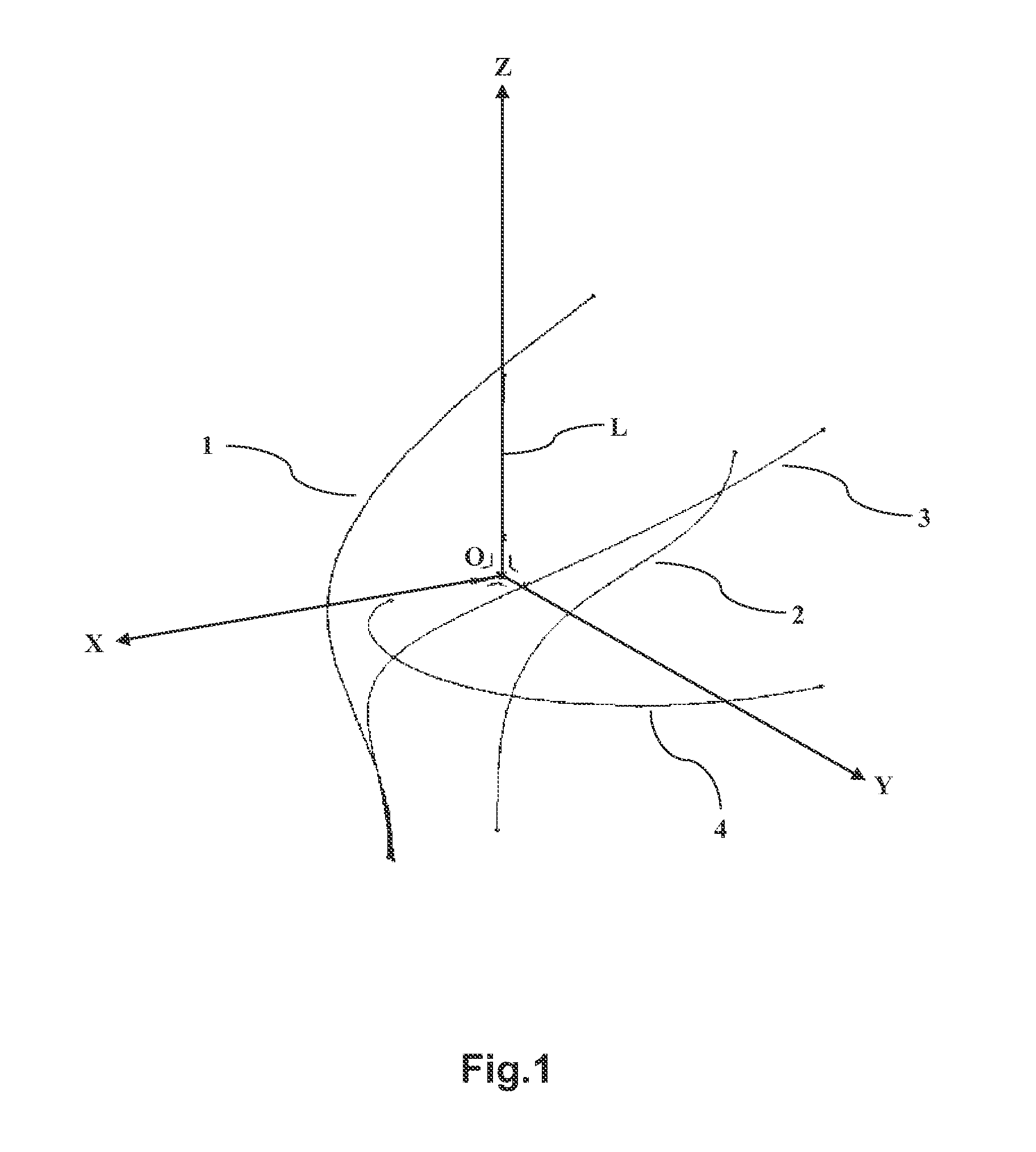
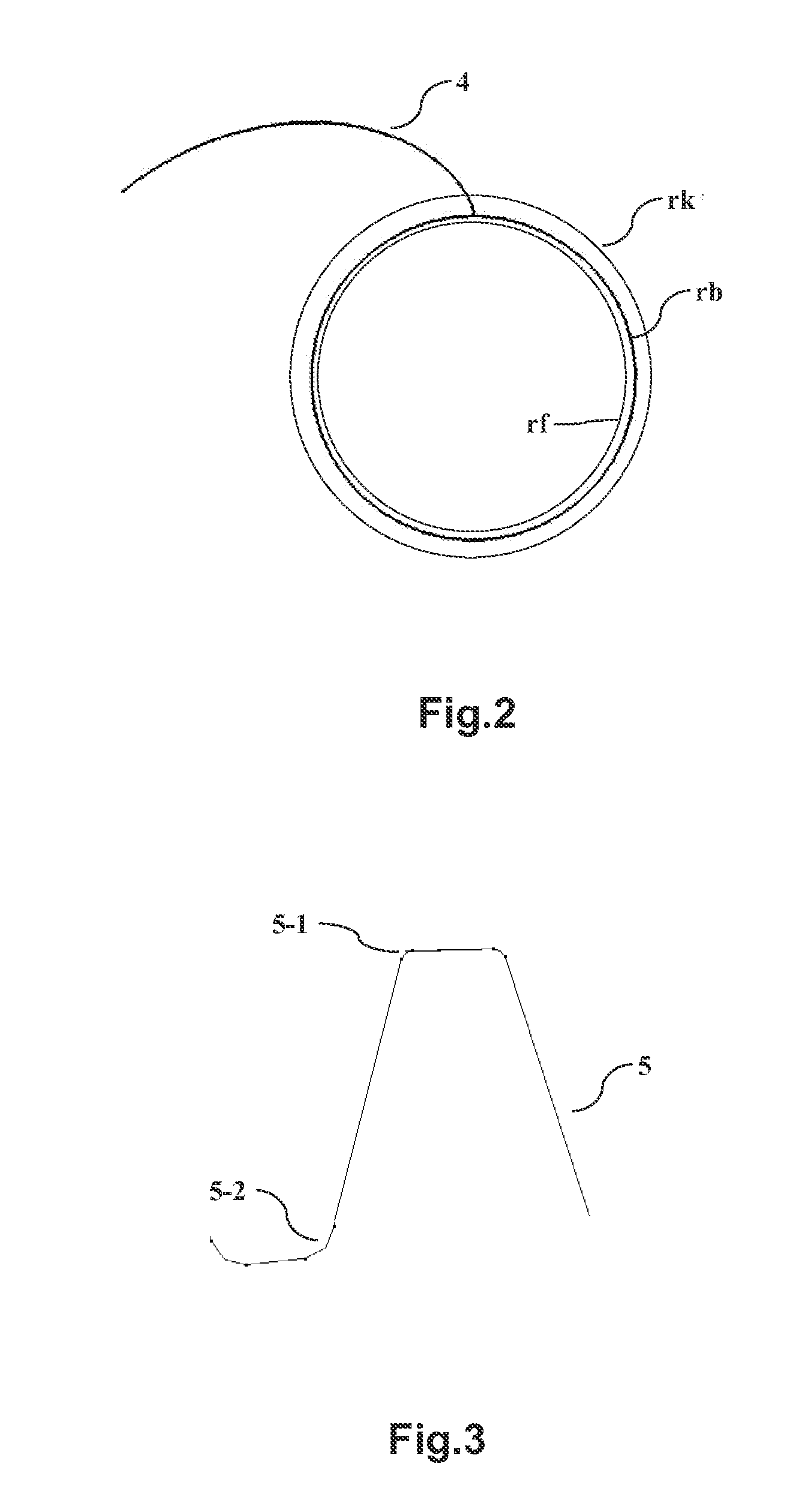
[0034]The gear construction method according to the present invention will be described in detail hereinafter with reference to FIGS. 1 to 6.

[0035]The first step: setting gear parameters.

[0036]For example, the following gear parameters may be set: the number of teeth z, a module m, a tooth width B, a pressure angle α, a tooth root coefficient C*, an addendum coefficient ha*. It should be appreciated by those skilled in the art that the gear parameters are not limited to the above parameters; instead they may be chosen appropriately according to various construction methods of a gear model.

[0037]The second step: constructing a three-dimensional coordinate system XYZ in...


PUM


Abstract

The present invention relates to a gear construction method, including the steps of: i) setting gear parameters and an XYZ coordinate system; ii) according to the gear parameters, creating a first curve associated with an involute of a tooth profile of a target tooth in an XZ plane, and creating a second curve associated with the involute of the tooth profile of the target tooth in a YZ plane; iii) combining the first curve with the second curve to form a third curve and projecting the third curve onto an XY plane to obtain the involute of the target tooth; and iv) constructing a tooth profile of the target tooth and form a solid model of the entire gear by using the involute. The present invention also relates to a digital apparatus associated with the above gear construction method.

Description


Claims


Application Information

Patent Timeline
Owner AIRBUS SAS
Why Eureka
Try Eureka